This is an outline of everything i did to complete the build of the Nexdome observatory, now called “The Orion Observatory” in my suburban home location. Its a bit long but hopefully detailed enough to assist others in this type of build. There are also two videos on the same topic, not quite as involved, at the end. Special thanks to an awesome community of fellow astronomers and observatory owners, whos valuable input helped make this all come together. Now I’m trying to gather all that I did and put it out there as a source of possible info for others.
Update 3/2/21: I’ve finally sorted the communications issues between Shutter and Rotator by switching Xbee units (see Part 16: Enhancements)
- Part 1: Background
- Part 2: Ground Breaking
- Part 3: Deck Materials/Flooring/Walls
- Part 4: Mount and Custom Mounting Plate
- Part 5: Deck Build Begins / Electrical Runs
- Part 6: Concrete Preparations / Rebar Cage
- Part 7: Deck Complete
- Part 8: Testing the EdgeED 11 OTA on CEM120
- Part 9: Nexdome Arrival and Setup
- Part 10: CloudWatcher AAG Setup and Software
- Part 11: Dome Software Configuration, Control, Scripts, Nina and Other Issues
- Part 12: Remaining NexDome Issues
- Part 13: Conclusion
- Part 14: NexDome Construction and Wrap Up YouTube Videos
- Part 15: Full List of Equipment and Accessories
- Part 16: Enhancements and Updates
Background
I live in the suburbs in a Bortle 5 sky zone (i think 19.8 magnitude or so on the scale), mainly due to a small shopping center pumping out light to my East 2 blocks away. I’m blocked to the direct west by trees (i can catch venus at certain times of the year in the west next to the trees though). To the north there is another smaller lot that puts up a bit of low angle light, but higher up its fine.
It had become clear we probably werent moving for at least 5-10 years, so it made more sense to just go for it from the current house.
Here is a pano shot looking due S (east to the left, and WSW on the right):

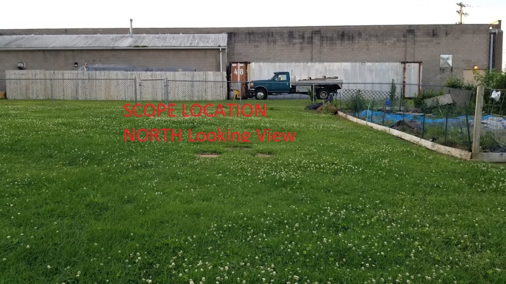
This is where i’ve been setting up the scope day after day, looking north (that light above their wooden fence does minorly light up part of the upper yard, but most targets aren’t North) (Update: i’ve tried asking the bowling alley to at least put a shield on the light to the left in the image, they said they would come up with something, though it sounds like all they want to do is put a yellow light in place of the white one):
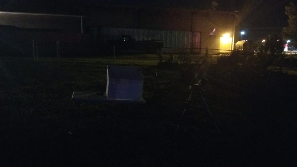
The light at dark:
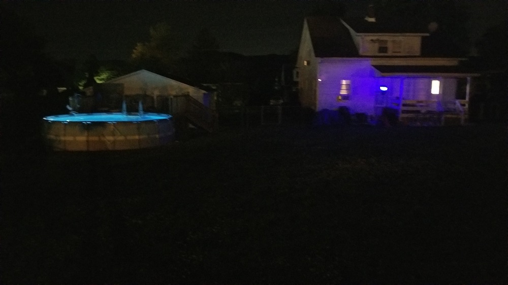
And looking south (i dont think my pool light hurts anything from that low level):
Ground Breaking
All that said I opted to go for the NexDome. I looked at other options, but it was the most economical for what it can do, with its higher walls, light blocking and cheaper overall to automate, by at least 3-4k.
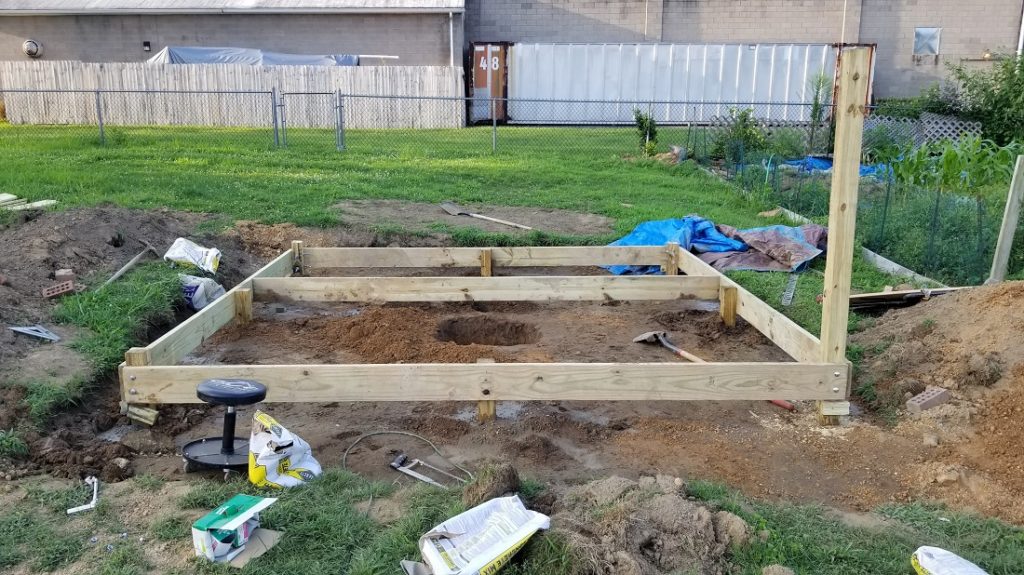
I decided i would do a 12×12 wooden deck as the flooring, along with a pier in the ground (concrete) extending up through the deck and isolated (24×24 footer).
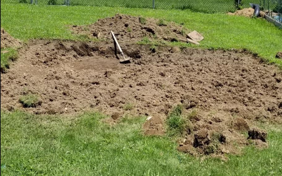
Here is a shot when i first began manually digging/leveling the ground:
I initially thought i would do concrete above ground preformed blocks so i could just pick up the deck and take it when moved. I decided that wasnt practical and I was concerned about any movement. In SW PA the winters can be harsh.
I had a ton of excess dirt. I ended up just redistributing in the garden and parts of the yard.
Here is the layout with some lines to show things:
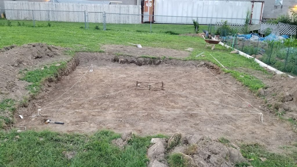
Here is the pier footer so far, dug down about 2.5 of 4 feet (manually, it wasn’t that bad till i hit clay, i will be able to finish by hand though). I did the first 3 feet or so by hand, the rest using a large post hole digger which I rented.
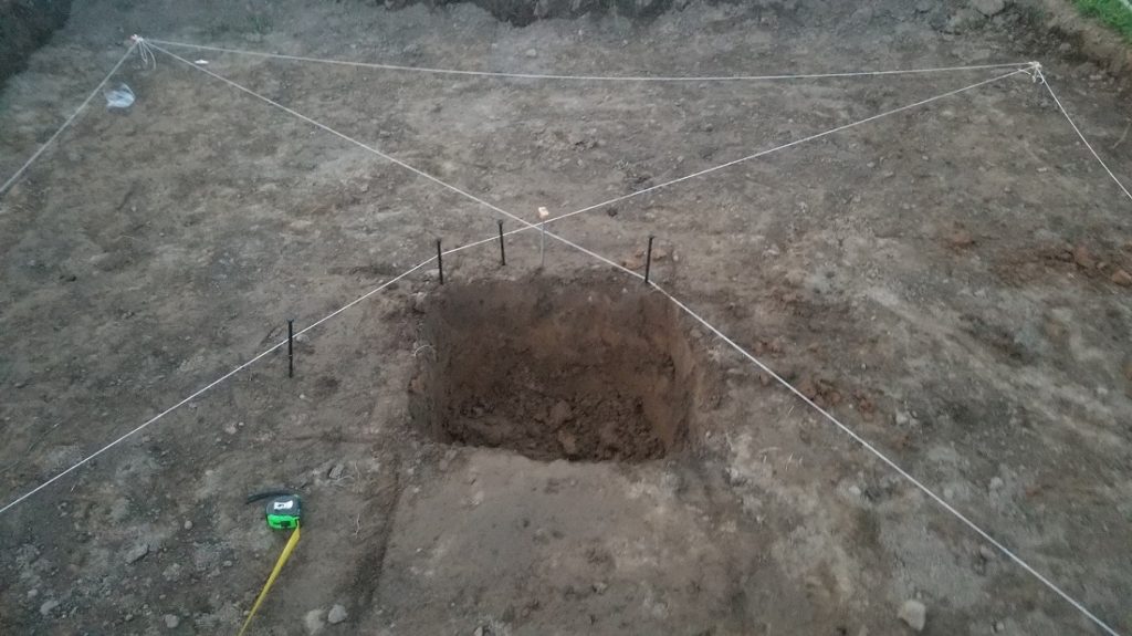
We have pretty easy going city codes, so i didn’t need to worry about the frame being 12″ or even 10″, however, i went with 8″ and for a low level deck really is plenty though you will get differing views out there.
The base of the frame was to be at most about 4″ off the ground, and that makes it 14″ above ground for the 5/4 board on top (decking planks).
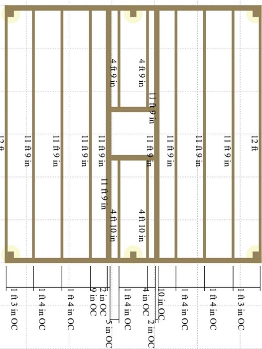
Here is a rough layout of the deck and joists that I had created beforehand. I didnt do double boards on the two sides as shown otherwise the same, 16″ on center for each joist. (there will be a post on each side of the middle area as well).
Deck Materials/Flooring/Walls
2x8x12″ framing board and joists x 14 (so 10 for joists/boxing in the pier area)
4x4x8 x 4 for posts (which ill dig down 2 feet which should be good enough, yes 4 foot is the frost line but our bigger pool deck only went down about 3 feet with 4 foot high posts and its been solid; i plan on wedging the posts in the hole temporarily and putting on the 2×8 board making it level and then adding 1/2 the hole with high strength quickcrete and then about 4 inches of water/1 gallon and let set making sure plumb) Ill do the frame on 2 sides so i can lay a 5/4 board across to get the exact deck level to be able to add the frame for the pier footer.
5/4 x 6 x12 footers x 27 **for the decking. There is debate here, once i have it up with the dome, i might consider laying plywood ontop of the 5/4 to seal off from critters and then use the interlocking foam mats everyone uses for flooring, along with rubber padding along the edges of the dome, as well as caulking on the outside of the dome (the 27th is a spare)
60lb high strength concrete mix (again, using 1/2 bag in each post hole)
2x4x8 x 4 : for creating a frame around the pier to pour the cement and keep it straight (pvc pier) and one piece to tap at the concrete as its being poured in.
3/4″ plywood sheathing 2×4 x 2 (for making the box around the pier 14″ high)
2×8″ 18 gauge triple zinc joist hangers x 16
Galvanized steel nails/hangers should be used, so these x 16
Deckmate 3″ ceramic 5lb screws (for screwing in joists and for the 5/4 boards up on top and temporary hold screws for posts before carriage bolts before cement)
1.5″ joist/framing nails galvanized 1lb
0.5″ hillman 8″ carriage bolts and nuts and washers
At each post two carriage bolts one above the other for support.
Steel rebar ties (for making hoops/loops around the rebar cage that ill make out of 4 rebar)
4′ rebar x 8 : this will be for 4 rebar each, a cage down in the footer hole (which will only make it to the edge of the surface) and also for inside the PVC pier which will start 3/4 the way up and extend out 1 foot down under the pier tube and insert into that 14″ area above ground
Hillman 5/8″ x 12 L bolts: These are for the mounting plate going down into the concrete, with the plate about 1″ above the PVC so there is room to tighten the nuts.
Hillman nylon lock nuts (zinc): x8 unsure if just these and washer or the standard nut + lock washer + washer (i didnt see stainless steel at lowes, my closest option around)
Hillman 5/8 split lock washers x8
Hillman 5/8 standard washers zinc plated? x 8
PVC 10″ diameter (originally 12) for the pier and 4 foot long initially: Online there are some sources that will ship, as cheap as $139.. I found a local source and it was $90 total for 4 feet, which got cut down to size
Possible flooring options:
96 square feet walmart foam tiles $69.99 (3/4″)
Wall foam for walls and the dome portion (to reduce humidity) 1/2″ style (used 3 sets of these and covered maybe 65% of the area)
Telescope Mount and Custom Made Mounting Plate
I opted to go with the CEM120 mount, for future proofing.
I started off with the 8SE in mind, but before the mount came I switched to the Edge 11 HD OTA.
This was my first official modern GEM (technically CEM with iOptron, for Center equatorial mount)
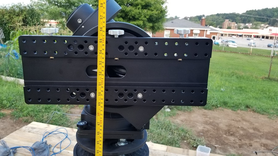
The CEM120 is a beast of a mount, supporting 115 lbs payload (though for AP probably only 75lbs max). I looked at hdx110 and other options, even the CEM60 before opting for this, based on payloads others have ended up at (beyond 50 or even 60lbs in some cases). I had to also account for the mount’s height which i believe was about 9.4 from its base up to the center of where the OTA is mounted. (This height is actually quite short compared to say the 20″ on a AP 1200GTO mount for instance) If I ever switch to a taller mount I’d have to probably slice the concrete pier, unless its only a few inches taller. This value subtracted from roughly 53″ and factoring in the custom plate/cage below, is how I arrived at what length to make the pier/pvc pipe section (factoring in how far off the ground the deck is as well).
There is a mount plate diagram online and it looks like this (this the oem one that comes with the cem120). I would have to have a local company fabricate another plate to join to this one.
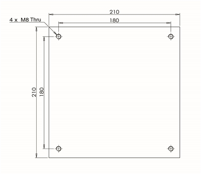
It boils down to the plate itself being around 8.25″ x 8.25 (diagonal around 11.67″). So the points of the square will be very close to the edge of the 10″ pvc.
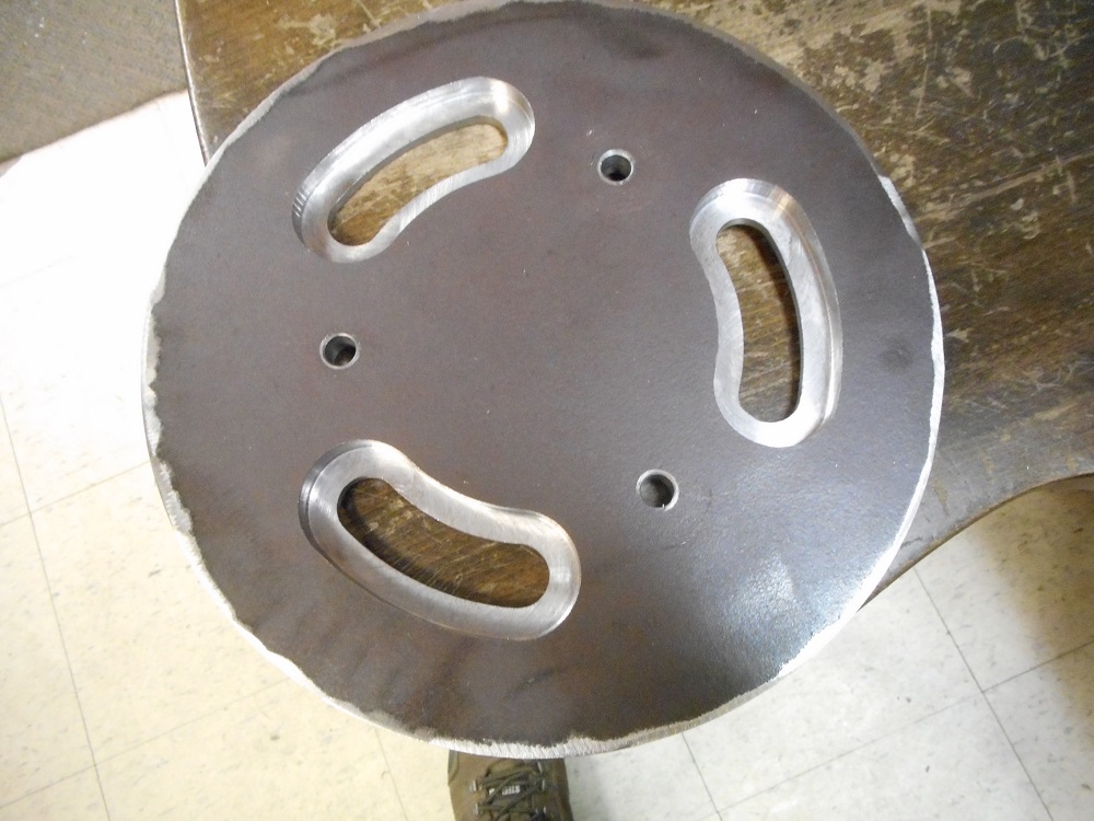
I ended up going with 1/2″ a36 steel rather than aluminum for the custom plate.
I was considering just using the local fabrication company make the $129 ioptron adapter plate but in the end I kept the plate, it was more cost effective at least with this local company.
The nexdome recommended height is 53″ from the ground to the center of the ota as in this photo (I believe i deliberately ended up at around 52.5″ though which has been fine).
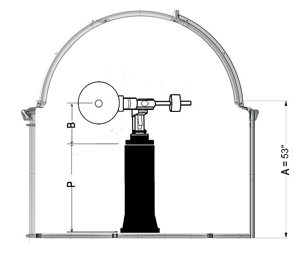
I was able to find a local fabrication place that can cut the 1/2″ a36 steel and put the holes in it and add offsets for the upper plate to sit on. The cost was around $140 (which was a bit high in comparison to what I’ve “heard”.
I went with 5/8″ bolts for the Anchor bolts.
The combination is a 2 plate solution.
I decided to make a mockup out of cardboard of the 10″ a36 steel plate that ill use for the lower plate as seen here
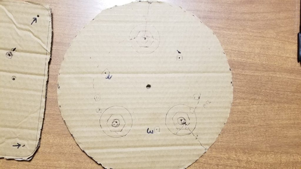

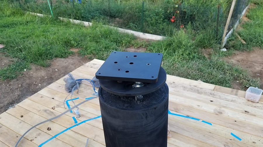
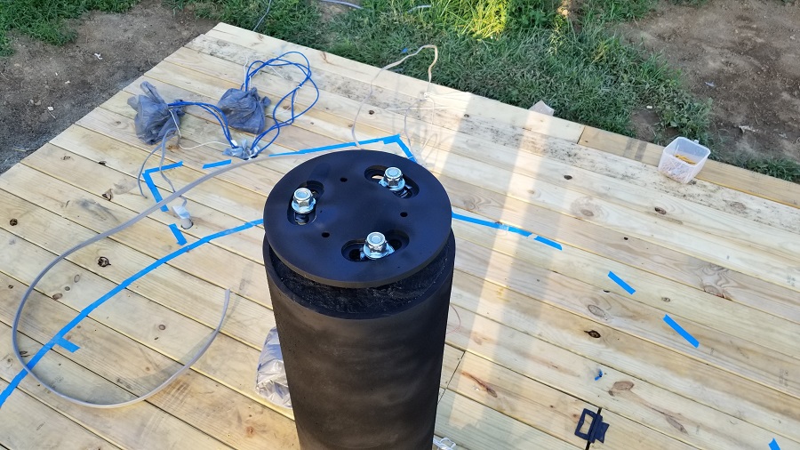
I’ve redone things and included the 5/8″ jbolts, nylon lock nuts on top, double washers and lock washers with regular nut on bottom. Double because if they can slot the plate to allow position changes on the bottom two jbolts it will firm them up.
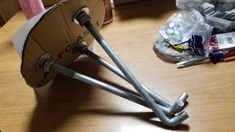
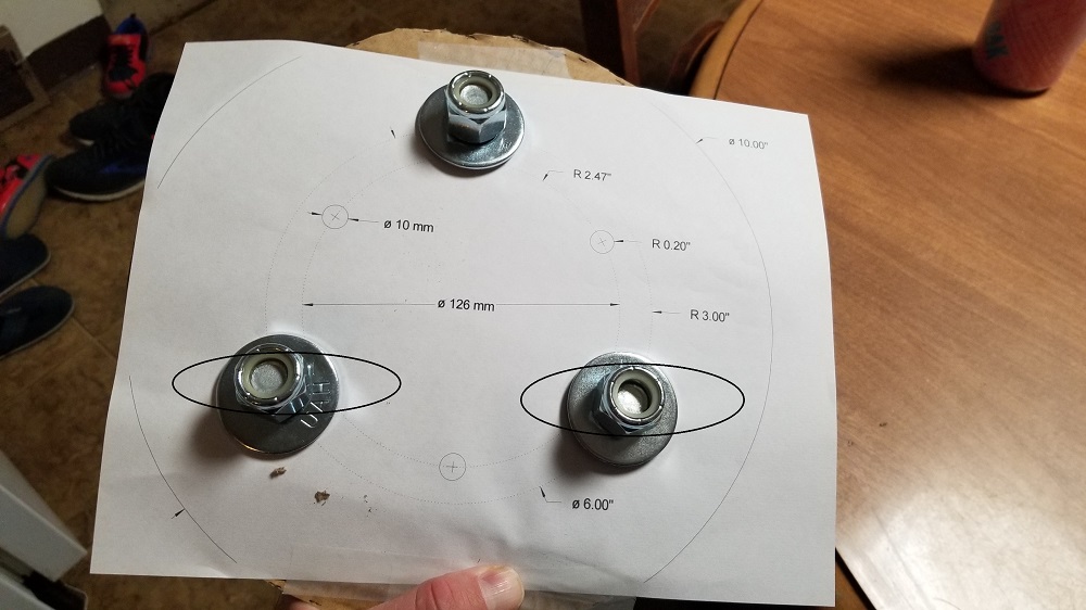
Once local fabricator completed the bottom plate, he mentioned that the washers i had included are too big (i think just for the top slots) as they were USS 5/8 washers. I had to go with SAE slightly smaller washers. I hope the smaller washers at least on top dont cause any issues.
I later painted the plate and used rustoleum flat black paint.
The fabricator made standoffs for in between that are 1.25″ in height, slightly more width between the plates than in the original idea, but I just wanted a tad more (and a tad lower pier, as ill make the jbolts stick out of the concrete slightly more).
Here is the photo of it before painting (1/2″ steel) with the slots for true north adjusting:
Deck Build Begins / Electrical Runs
Frame in place (mostly) tonight, more bolts to drill.
My original target was 4″ above ground below the joists (2×8’s) but i went a little higher to allow for some conduit running if not just going through joists.
Back end is an avg of 5″ and front about 6.5.
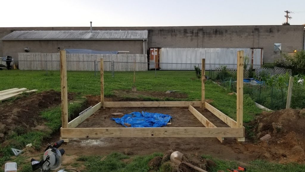
Im likely to leave the front right post as is and not saw flat, as i could use it for a security camera and a power box.
I had to rewire my garage subpanel because an electrician shortcutted it years ago with 10-2 wiring from the main. The wiring should have been 10-3 with ground.
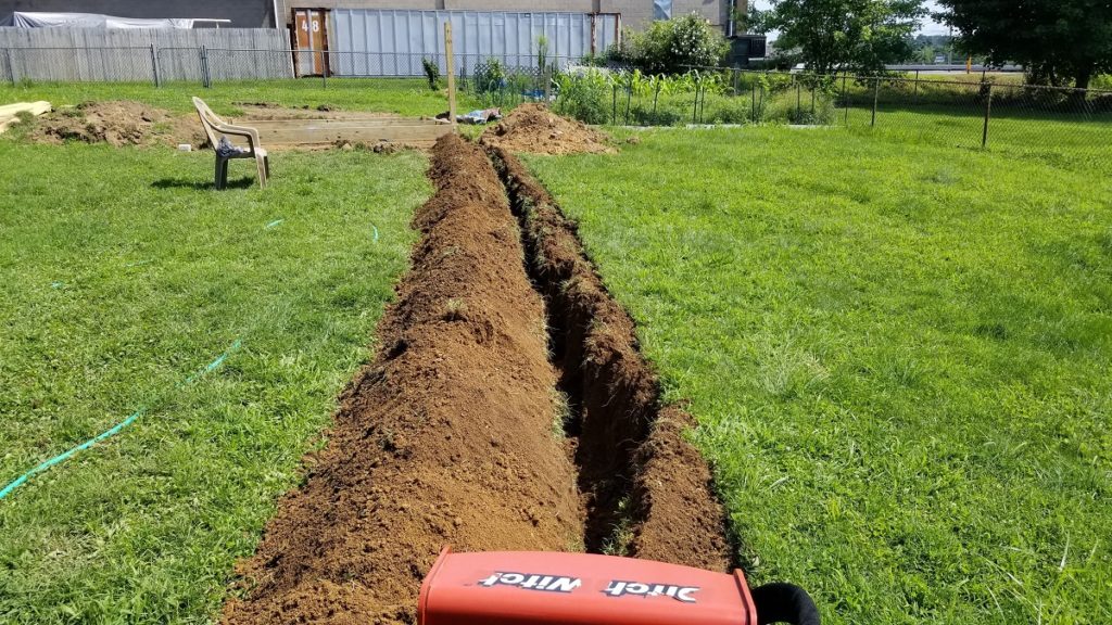
So today I rented a ditch witch which the local ace place delivers. Total cost to have delivered for 4 hours around $175 with the delivery fee i think it was.
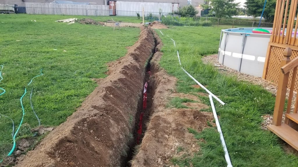
I trenched the path from right corner of the deck, which now has a good deal more done, including 8 of 10 posts in the ground.
My wiring for the observatory is going to come from the main panel in the house and on 10-3 with a ground as well. Cost around $1/ft for uf-b burial type, down 24″ with caution tape on top. I ran a section back to the garage to fix the mess there. In the garage/house will be a junction box on the other side of the wall followed by romex cable (same 10-3 with ground to the breakers).
At the deck post i’m using an LB electrical conduit (1″).
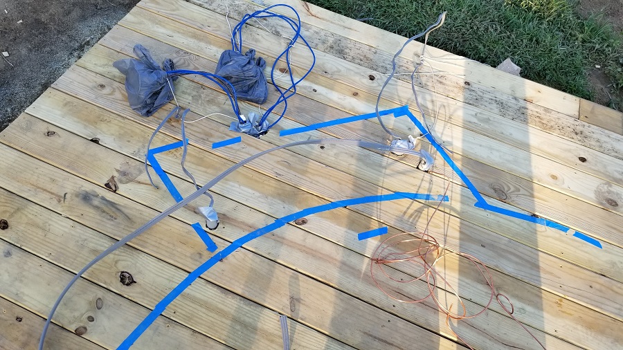
The data is being run via electrical conduit, 1.5″ for 3 gigabit ethernet cables and one bnc cable for a camera, along with a fish rope that will be left in case more is needed in the future.
I’m using an LB Connector box at the deck and one going through the wall at the house (1.5″)
I needed at least 10 sections of the 10 foot pvc 1.5 (roughly $6 per pipe) plus some added couplers and 90 bends.
Both the electrician and the local supply shop agreed since the dome is the highest structure in the top of the yard, despite there being a ground at the main and flowing through, that i should have a ground rod up at the deck as well. An 8 foot cooper one along with 6 gauge copper is being layed in the ditch up there or driven into the ground.
So the ditch layering is like this:
24″ deep, first the ufb wire
Cover that with about 3″ or 4″ of dirt
Then lay the caution tape.
On top of this is the 1.5″ pipe for data.
At the deck post beyond the lb is going to be a junction box on the outer post and from there under the deck ill wire to the pier and branch off to outlets as well as the breaker box/panel (probably 2 breakers).
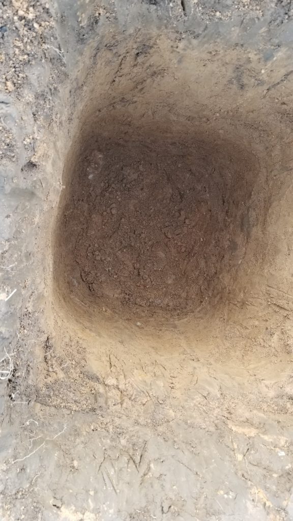
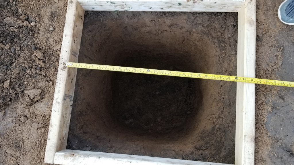
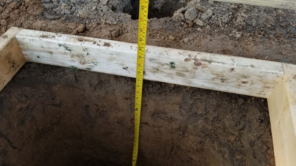
The pier footer is at 43 of 48″ deep and 2foot by 2foot wide at this point. I might just go with this for the footer, it should be deep enough. All the posts on the floating deck around 26″ deep with 2 bags of concrete per the outer 4 and slightly less deep and about 1.5 bags per post for the middle 3 supports.
I started to hit alot of rock, so it was hard to bell out the bottom wider, as it should be. I was using a post hole digger (one man) for much of the last 20″ of this, i happened to have already rented it for the other 4 holes so i figured why not.
I’ve also heard that it might be a good idea to put insect netting below the deck boards. That might be something else i add.
Possibly something like this netting here 4×7 for $12 at lowes x2 or this on amazon for $20
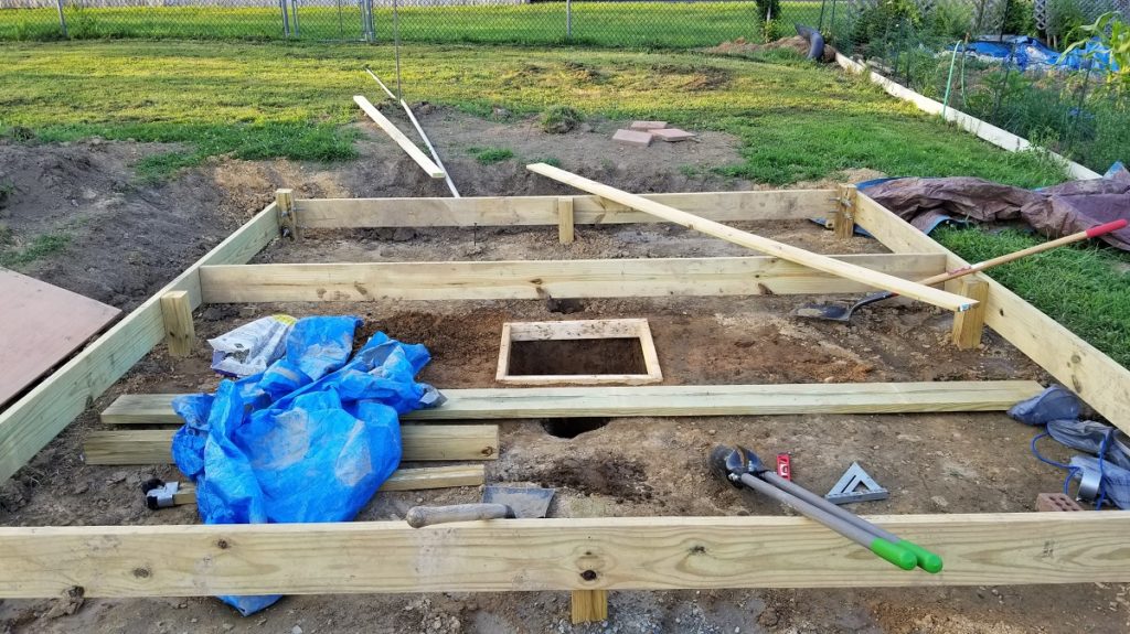
I’ve settled on the frame of the pier hole being around 1″ above ground. I got it put in tonight but its off center, nothing i can do about it. I could add another 2×4 to the right but there would be concrete under that 2×4. I could try moving it left, but it would be above air on the right. I did manage to bell out the bottom slightly, overall its around 43″ deep.
I havent decided whether ill try to run pvc down the center of the 10″ pvc pier or not (one for data one for power). I might skip it and just strap any wires onto the side.
Either way ill have flooring over the footer but not touching the footer and not contacting the 10″ pvc pier when done.
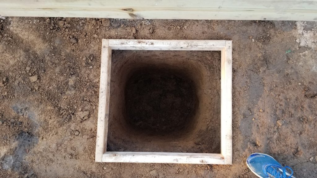
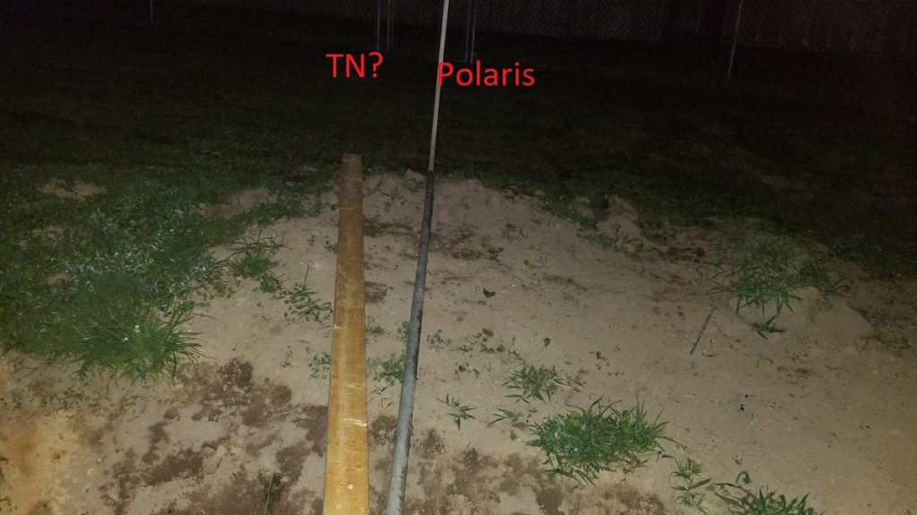
I also took a shot at true north calculations. I placed my 8se scope / tripod behind the center of the hole, found polaris and came straight down to level. I was able to target the rear fence and stick a stake in there, then use a laser pointer and put another directly in line to create an arrow.
I then tried a compass app on android. It had it more to the left, as shown by the wood in the photo. I’m going to go with the polaris line of sight and hopefully the slots in the lower mount will be good enough to adjust if off. In the end I think it was very close.
Concrete Preparations/Cage Creation
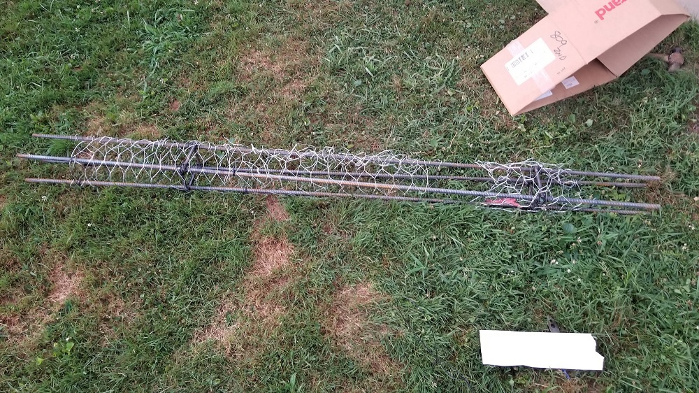
I took a combination of peoples ideas and ended up doing this rebar cage twice. On rev 2 i went with an $8 roll of galvanized chicken wire from lowes to use to hold it together.
But, to also aid things, i initially pounded all 4 stakes into the ground inside a box so i could measure out the distances and set cross bars in addition.
Here is what that looked like:
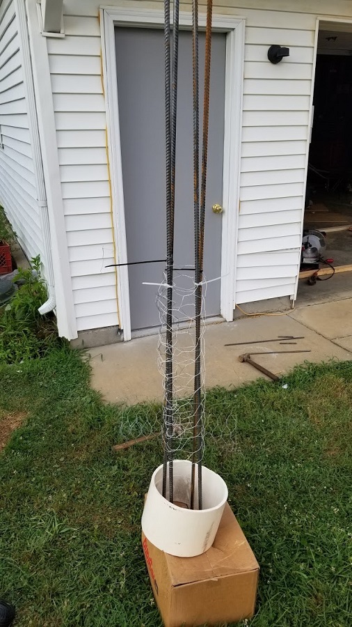
I set the distance between the bars at around 4.5″, this way I will be able to get a 2×4 down in there to mix up the concrete as its poured to prevent bubbles and air.
I ended up using both the rebar for holding it together and chickenwire:
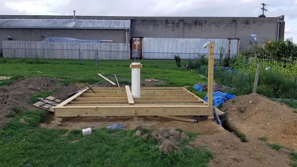
I placed the 10″ pvc frame that i made around the hole in the deck:
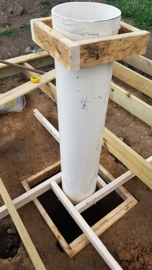
The bottom of the pvc pipe will be submerged 3/4″ into the concrete footer.
I also added gravel to the bottom then used wire rebar holders and placed 2 rebar in the holders allowing for the center to come down the middle.
My concern here is that the horizontal ends of at least 1 or 2 of the end points are lightly touching the soil, so i cut them a tad shorter to not touch in the end.
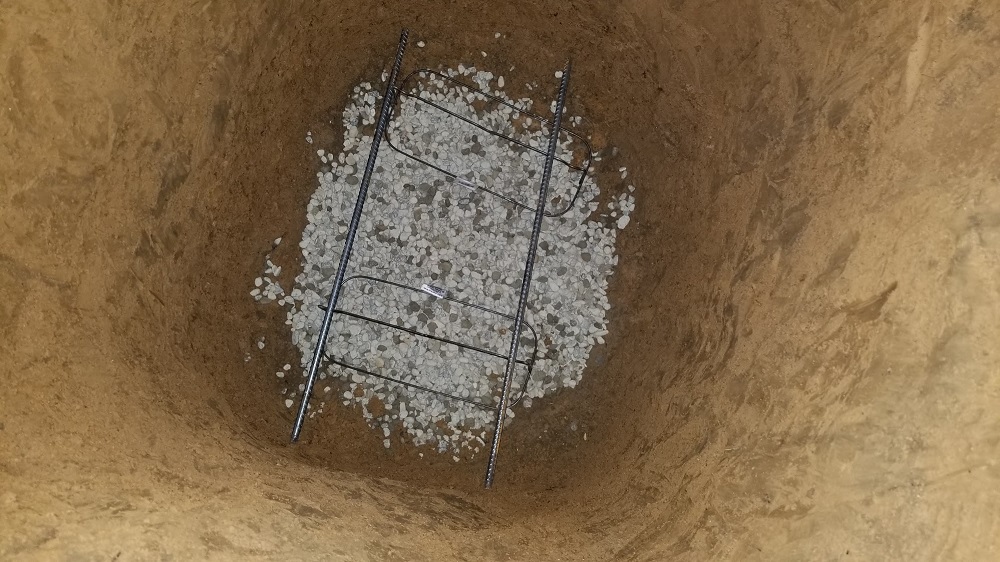
I then moved the platform over the hole, centering it as best i can and lowered the rebar cage down in.
It works out to around 1.75″ or more between the rebar and the sides of the pvc. I have about 9″ of jbolt that will be into the concrete which will end up just above the rebar cage.
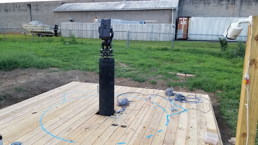
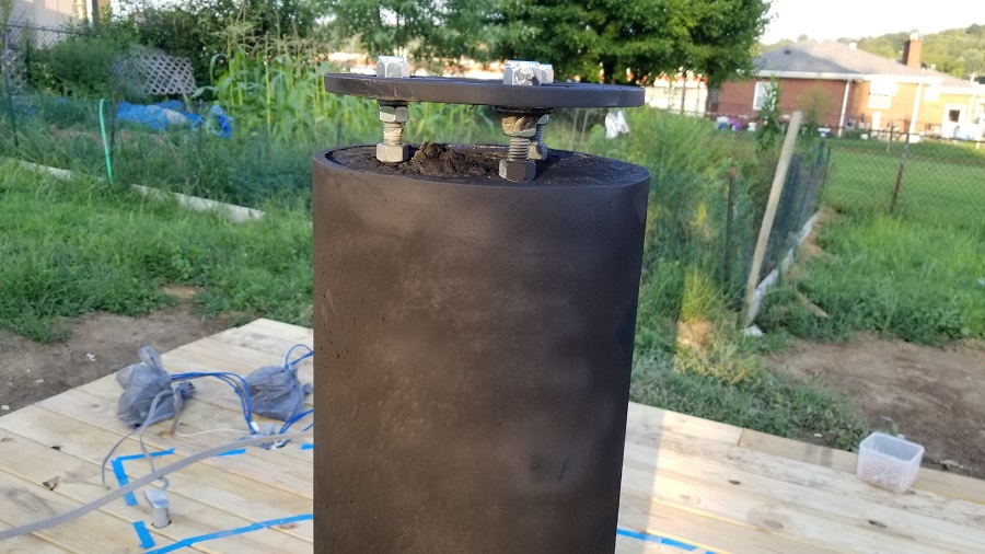
I did a test of the height over everything. The floorboards sit 13″ above the ground. The pvc pipe was roughly 52.5 inches. The mount combo of plates sits about 4.5″ above the pvc and the ra/dec point is 9.40 above that, this works out to 52.9″ (the wall is 53, was the original target). I actually wanted to drop this another 1″, as now i’ve acquired a new celestron edge 11 scope (and hyperstar, though still researching a camera), so i wanted some insurance on distances. I can adjust the bolts on the mounting plate to go lower by 1-2″ if needed though. In the end after adjusting i think i am at 52.5″.
Later I used 220 grit sandpaper over the pvc, then an acetone wipe down, then Krylon Fusion Matte Black spray paint (2 coats) to paint it.
I moved the platform over the hole, centering it as best i can and lowered the rebar cage down in.
It works out to around 1.75″ or more between the rebar and the sides of the pvc. I have about 9″ of jbolt that will be into the concrete which will end up just above the rebar cage.
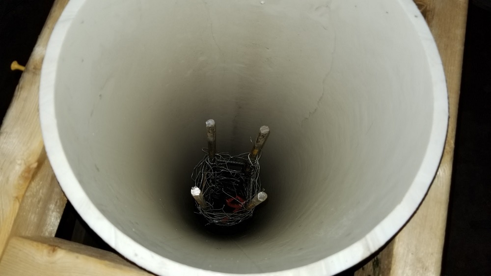
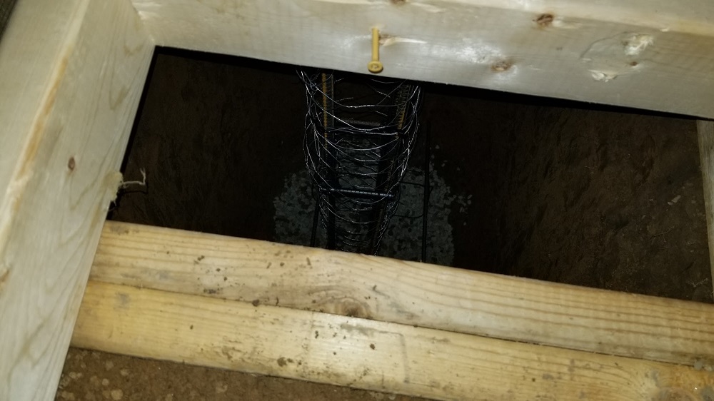
I had checked on cement pricing for 22ish bags of 0.64cu ft high strength (4000+) cement + renting a mixer and delivery and it was around $220. I found a local delivery truck for $280 and they handled the delivery. They used a chute behind my yard into a wheel barrow and we rolled it across a few boards put together right up to the hole.
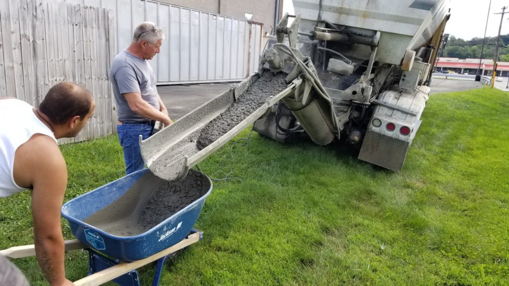
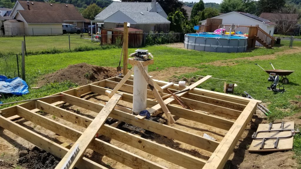
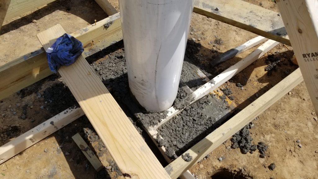
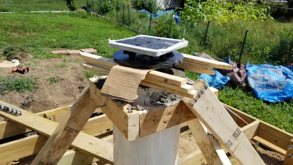

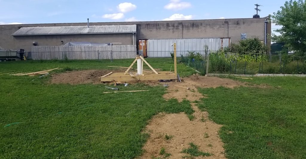
We used a 2×4 down the middle tamping it at times. I also took a hammer to the base. My cousin (contractor) felt it was ok even without the 2×4 tamping, but i was a bit nervous and ocd about it. Also, constant adjusting of the central rebar structure in the middle kept things moving around too. I waited at least 24 hours and then took the support boards/forms off of the pvc I decided to leave the 2x4s in the ground even though untreated wood. Shouldn’t be an issue i dont think.
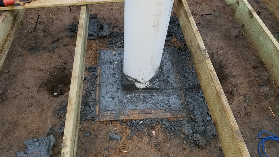
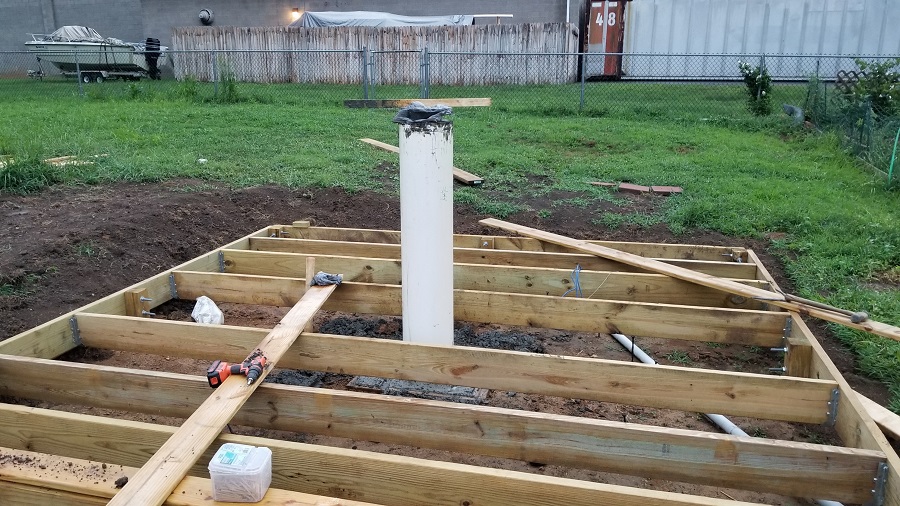
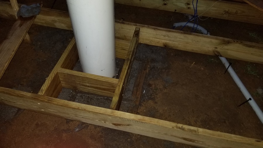
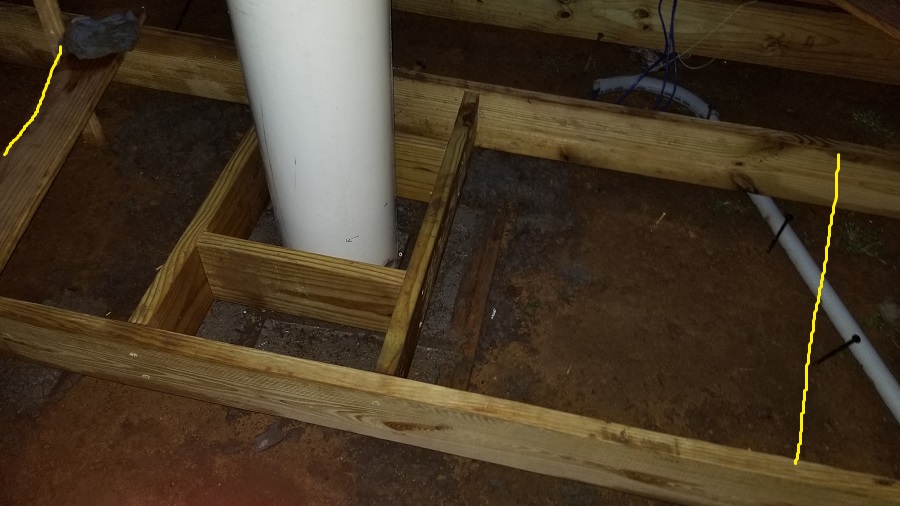
Ill use a 1.5″ pipe for the power and also a string left inside, to maybe later pull 12v wires if need be (its been mentioned about running 12v, but i’m unsure how/where that would be used).
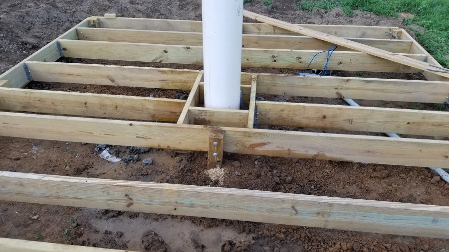
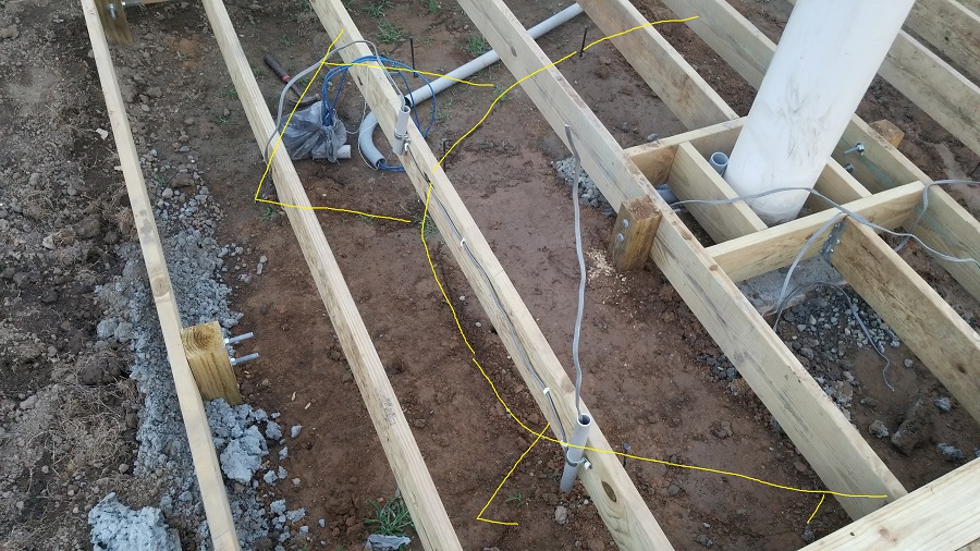
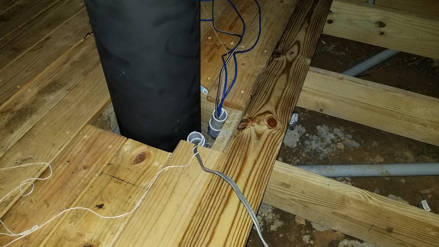
I used some tubing to hide the bay to bay wiring to prevent animal chewing per everyone’s suggestions, which makes sense. I also decided to just use the pvc i had on hand to channel the ufb to the bays as well and to the pier. One thing, i do have some of it off the ground, though much of it rests on the ground under the deck. Its sealed or will be completely sealed so i dont think this is an issue at all, it was just easier than trying to do hole saw cuts through the joists and clips are next to impossible to attach being so close to the ground.
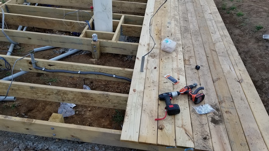
I took the boards pretty close to the pier, a few finger lengths distance, but not close enough that contact should ever occur. Ill probably put some sort of foam in this gap, then over the whole dome floor area ill have bug netting then the 3/4 foam flooring.
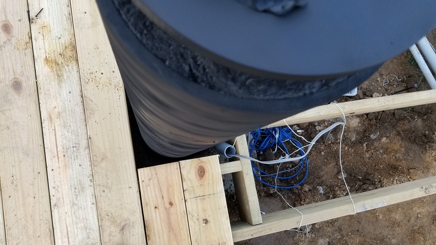
I also gave the pier a first coat of pain (fusion paint matte black), after sanding and using mineral spirits on the pvc first. I’ll need to do another coat because of the wavy initial pattern, though in a way i think its kinda cool that way.

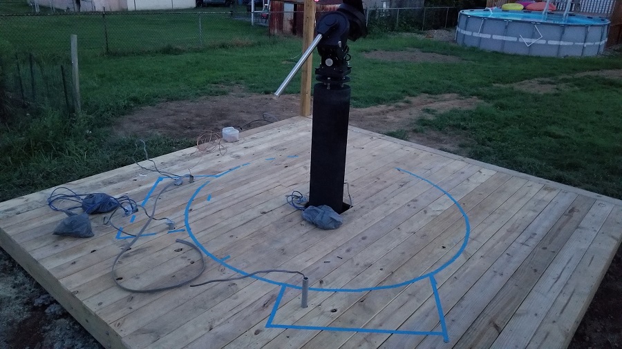
Deck Complete
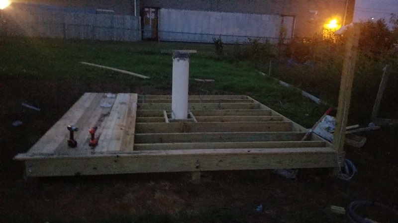
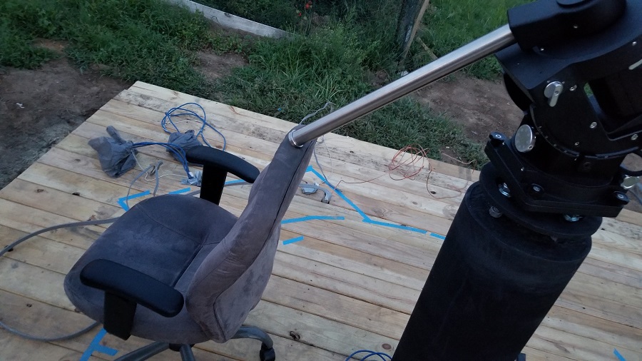
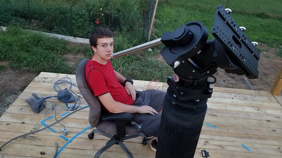
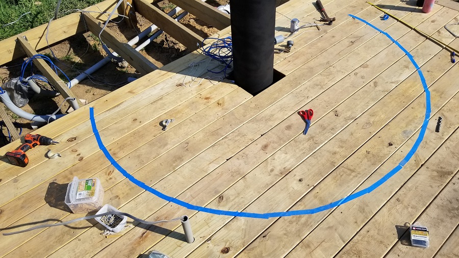
As you can see in the pics, i put the bays on the side where the counter weight shaft is locate (ultimately the position of at least the one bay shifted a bit). The back right bay with the most wiring, is the one i envisioned having the lcd and keyboard and chair in front of most of the time (the eastern bay became the toolbox/electrical panel area, while the north facing one became the lcd/keyboard/dehumidifier bay).
Testing the EdgeED 11 OTA/Mount
Back in august I put the Celestron 11 Edge HD on its mount and did some testing for the first time. An exciting moment.
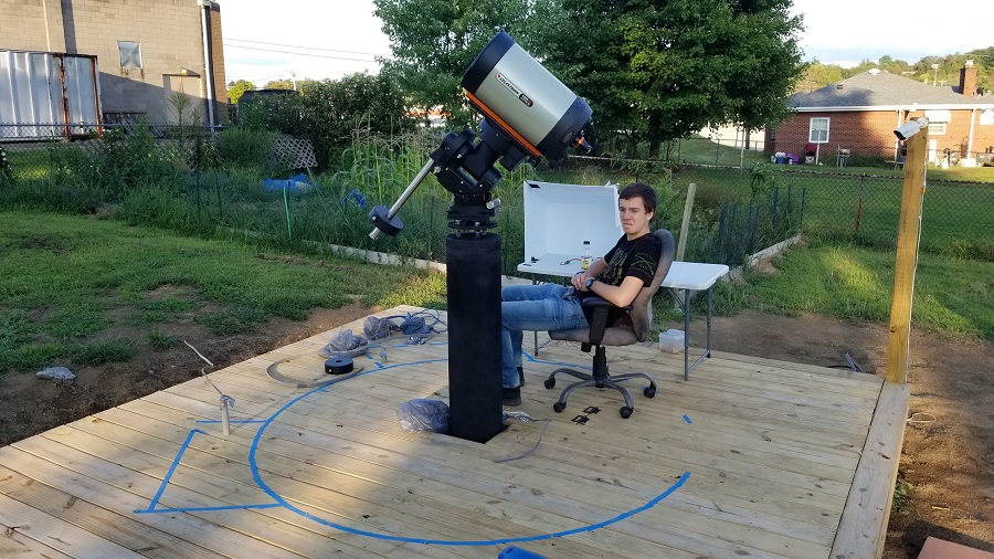
I spent some time learning the basics of the GEM mount (my first real one, previously i had a home made one many years ago). Technically ioptron calls their mounts Center Equatorial Mount or CEM.
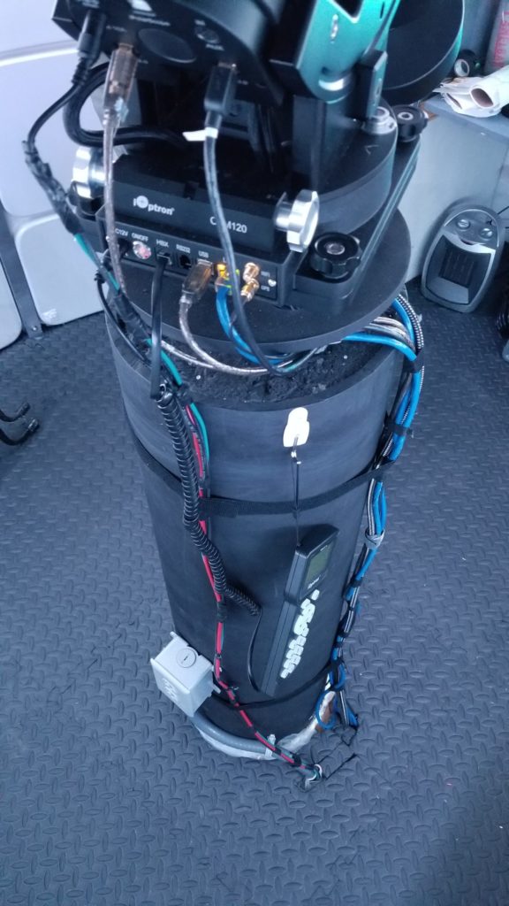
Once the dome was in place, i had to do alot of wiring related the OTA.
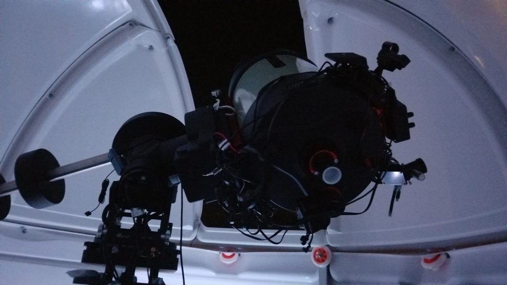
Nexdome Arrival and Setup
The Nexdome arrived on Oct 2nd and was originally ordered around July 16th.
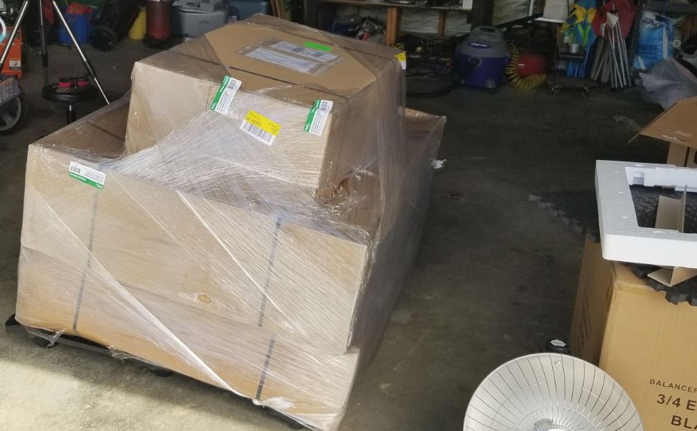
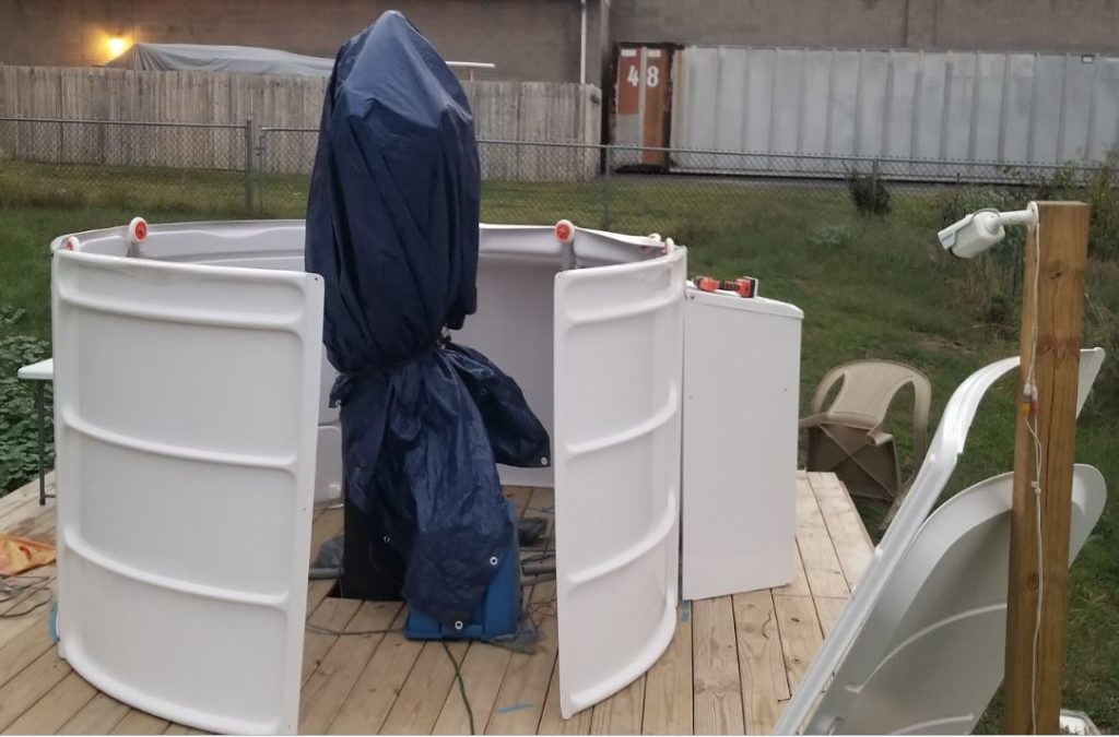
Everything came intact, no issues with the shipment.
Setup was somewhat painful, i did most of it by myself, particularly the dome portion, which is really meant for 2 people. In retrospect, i wish i had did a once over on the dome shape to make sure it was perfectly round and should have probably used a level and measured the walls to ensure they were also perfectly round. I’ve since worked through most of those related issues, however.
I think the interior size ended up a little wider than expected, as i was able to push the walls out beyond my line i had made.
I ended up going with the bays at the back, figuring it was better to be behind the CW bar than on the sides or out in front to avoid striking the camera train unexpectedly.
So the bay in the back left will be for the LCD screen/keyboard, while the bay in the back right will hold a tool chest and on the sides i will use existing holes to mount boards to attach the mini pc, remote web power unit, dc generator.
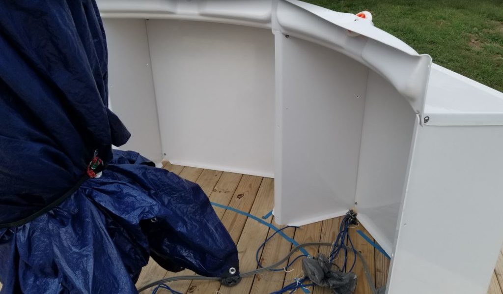
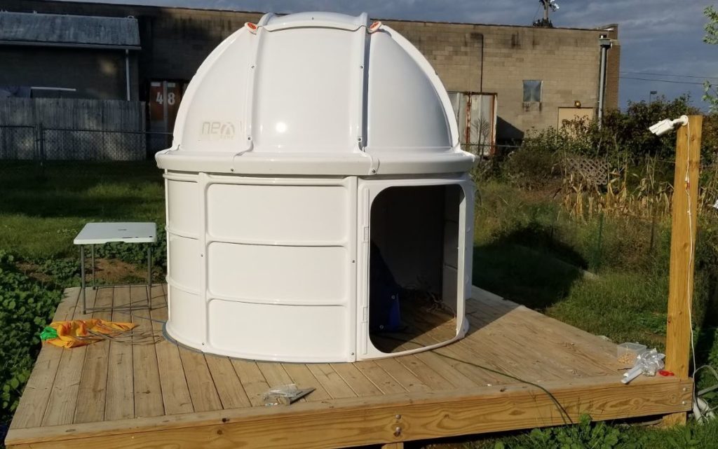
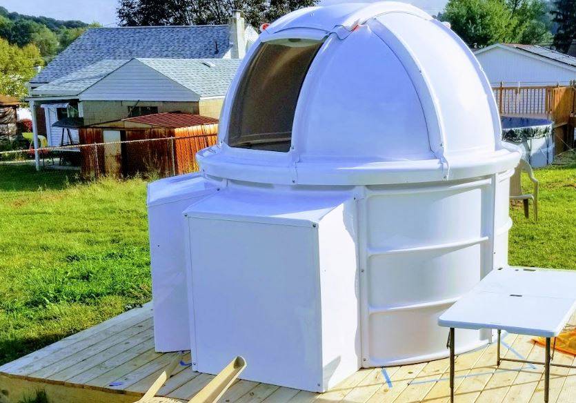
In a few photos below you can see the $129 tool chest i purchased at lowes (4 drawers), along with about $60 in pluckable foam (barely enough for maybe 2 drawers but proved to be enough).
Only issue is that i ran everything to the “tool chest” bay, so ill need to run a power cord and hdmi and usb cable for keyboard mouse to the left bay, maybe along the bottom either under the foam mat tiling or along the wall using stick on clips.
I had forgot to put the L brackets on for tethering to the deck. I later added those.
For the plywood in the bays on the left and right sides, i used 1/2″ sanded plywood and cut 2 holes in the top to line up with the existing bay holes and at the bottom a bracket to the floor. Before attached, i brushed on white stain/paint to the wood to prevent it from going bad from condensation (not treated plywood, i couldnt find treated in anything that was less than 3/4″ thick).
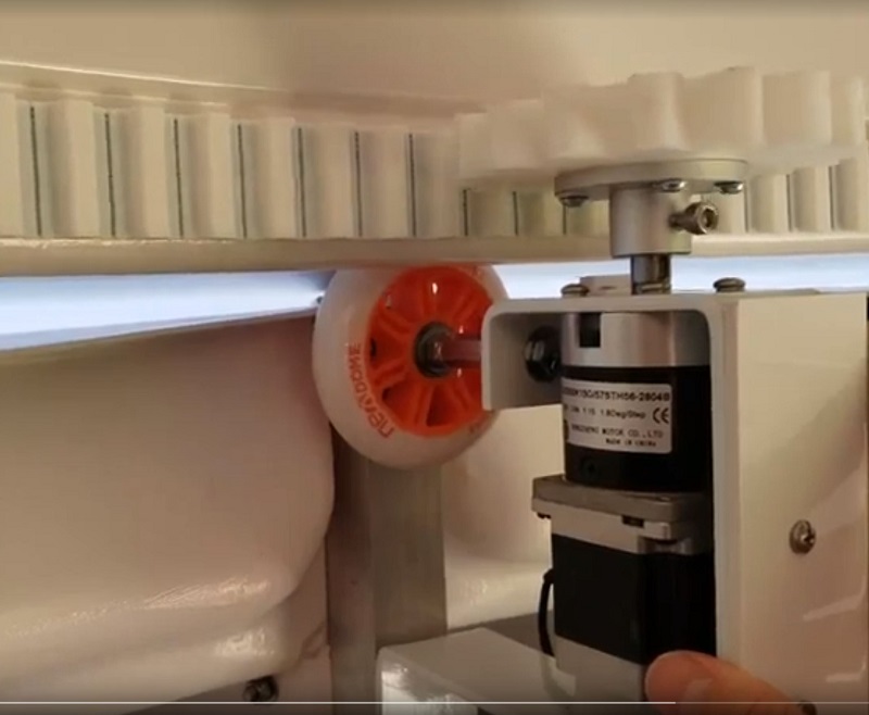
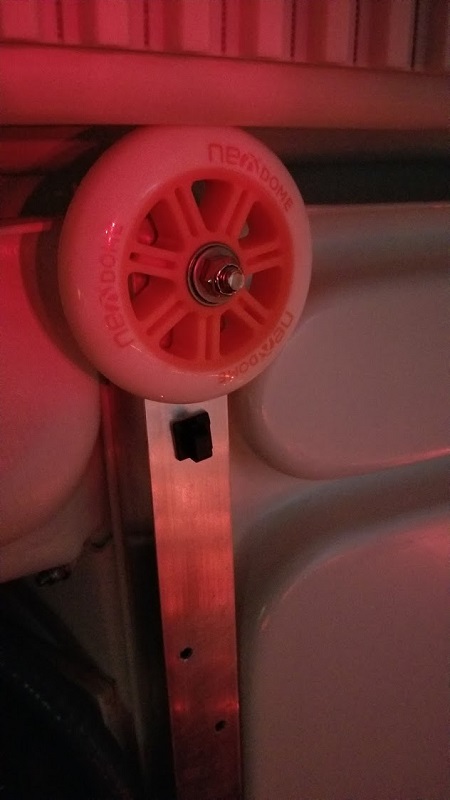
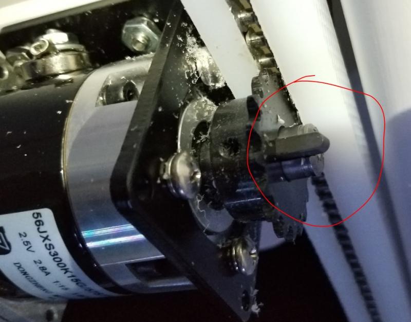
Next up was the dome rotator and track. I got the track installed, no issue, motor mounted no issue, motor connected to the wheel via the bolt, no issue. But occasionally the cog on the motor would lose grip. This was later fixed by putting the bolt directly against the wheel (taking the nut off).
This seemed to work, full rotation no issues after taking that nut off and also by pounding out some of the posts because they were inward a tad too far.
When i first had the grip issue on the cog/motor I had decided to use 3M tape in those areas to “thicken” up the track to get it closer to the teeth. In retrospect this was a bad idea putting the tape under there to thicken it, i actually ended up putting screws at random spots as the track came off and bubbled outward colliding with the charger holder at one point. I also used epoxy under the track in spots which worked as well.
Here is a shot of the motor and its connector to the wheel (i ended up removing the nut on the wheel solved all cog slip issues).
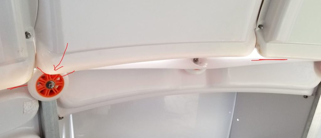
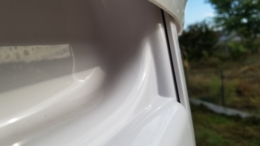
The other issue is the dome rotation, in spots the gap between panels is slightly higher on one side versus the other (see photo above) so the dome bumps going over the wheels. The bumps can be fixed using mold-able Sugru glue or JB Plastic Weld. I thought all was well, but in recent days I’m finding that the bump actually causes the motor to seize and the azimuth values get botched and cause slot alignment issues. Ill attempt to fix by adding the moldable glue to the gaps that catch when the wheel rides up on the lip (only in this one area).
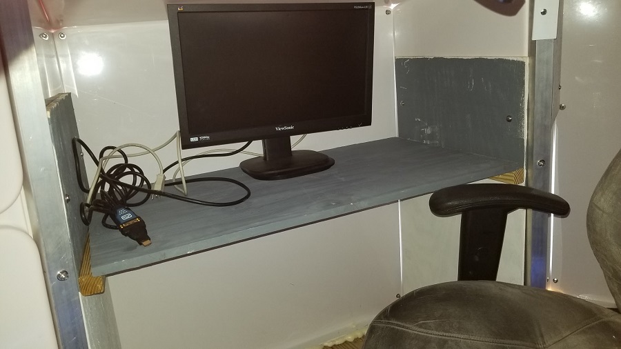
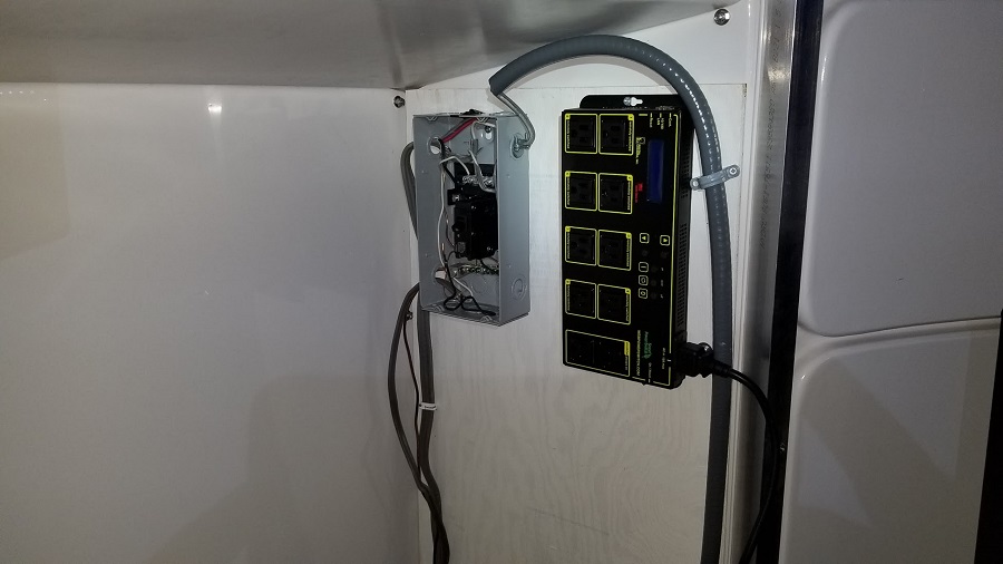
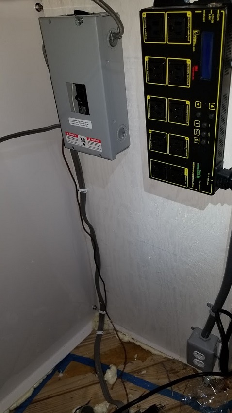
Above : I will be putting the mini pc on this panel, the right panel the dc generator along with the web control unit and power panel.
Then under the LCD shelf on the right ill put another outlet.
Ill only have 3 USB cables coming from the mount under the floor in pvc (2 usb 2.0’s and 1 usb 3.0) along with an ethernet and the dc from two anderson poles off the rigger runner connected to the dc generator (so the dc generator powers the scope and scope accessories ports only). I eventually added a usb 3.0 hub directly to the mount to deal with usb 2.0 port issues. I’m now using the Rigel Systems nStep focuser on the knob and it had some issues with the Cem120’s usb 2.0 ports not providing any power (only the usb 3.0 single port was powered). So I added the usb 3.0 hub.
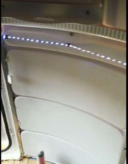
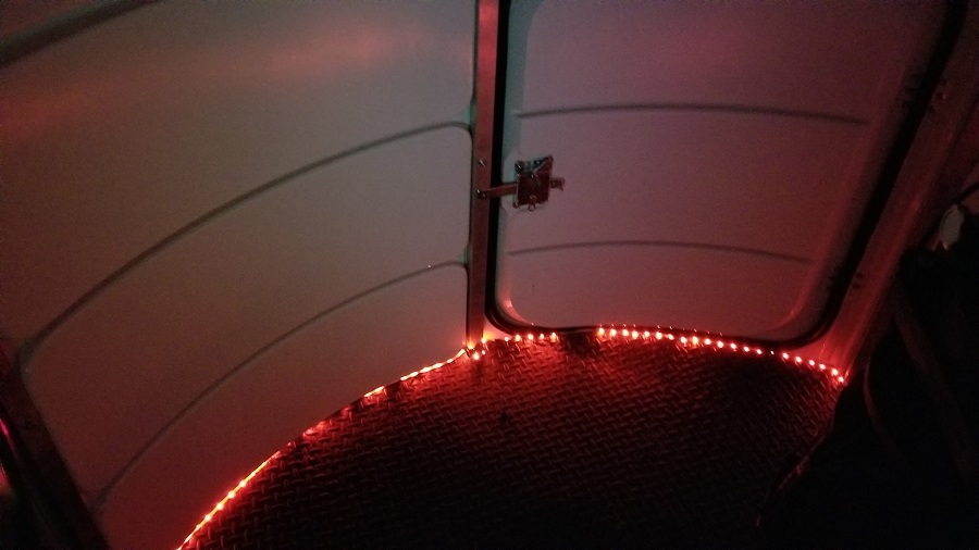
Im also not completely satisfied with the LED lights I got from amazon (for $29). They dont seem very bright when using white to see things in the dome and the placement isnt the greatest when it was up higher, on the floor its better at least when red, but for seeing higher would have been better. I may later add another strip along the top again just for working on things.
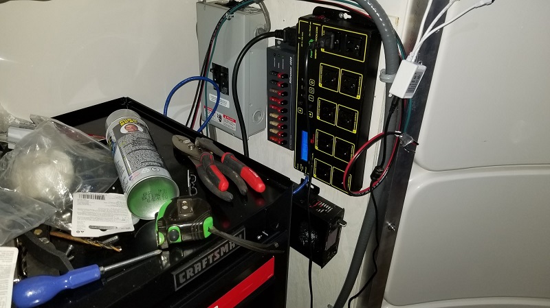
Tool chest area/electrical: The dc unit/rig runner will only power the mount power 5amp and mount accessories 10amp, i have 16 gauge wire going from here to the scope for those and ill use 18 gauge between the dc unit and rig runner. I set the dc unit to around 13.5 volts, probably resulting in a voltage of around 12.5 or so (or whatever it takes to hit this number to be safe).
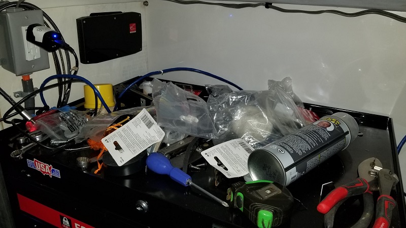
Just some notes on the battle against condensation. I started off trying the fan idea, by using the stanley fan on medium and let it run all night on one occasion, woke up to find that the mount didnt have any moisture (dome humidity still peaked at 90% though, even in the toolbox drawers where i have my equipment in pluckable foam). However on another test the mount was still wet, so the fan didnt help. Ultimately it was the mentioned dehumidifer thats kept it dry every morning. Dry is the key, not so much the humidity values. (The ecowit sensor that has a web interface always reports higher numbers than the physical digital unit i’ve tested).
Worth mentioning that this was the smaller dehumidifer i first tried:
Eva 2400: $107 shipped after discount code. It states it sucks out about 25oz of water at 85% RH at 86F i think. It didnt do much/help.
The one i use now, this Amazon 30 pint dehumidifier $134 uses around 170 watts of energy and goes to power save by setting the low end to 40 at times.
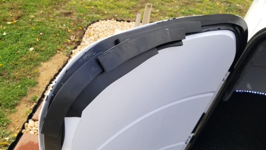
So far too, my flooring/caulking is working out, heavy rains etc, the only issue i’m having is that the door is still leaking in one small spot, resulting in a small puddle (3″ or so) just to right of door about 4″ inward as you come in. The extra foam on the door didnt help with the leaking, ultimately i cut a garbage bag 4″ strip and used it over the top seal, no water has leaked since. You can see the flap in some of the photos below near the end of the article.
Around the pier on the floor i opted to just fill the hole below with pieces of foam floaties followed by steel wool, then a layer of spray foam.
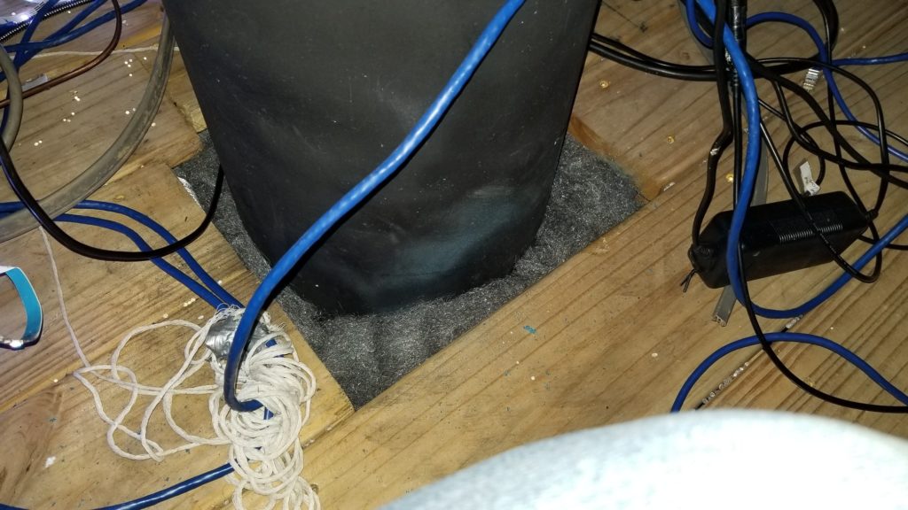
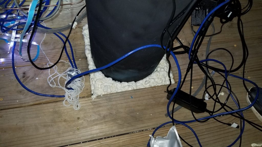
I had created a hinged compartment next to the pvc pipe for putting DC adapters inside, but ultimately all power got ran to the tool chest / computer bay.
You can also see the foam that protrudes on the outside of the bays. I later cut this and applied the PL Max caulking to the outside and also used PL Max Premium on the inside along the floor.
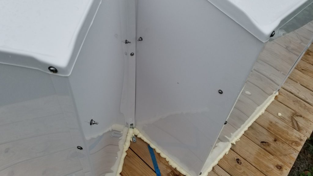
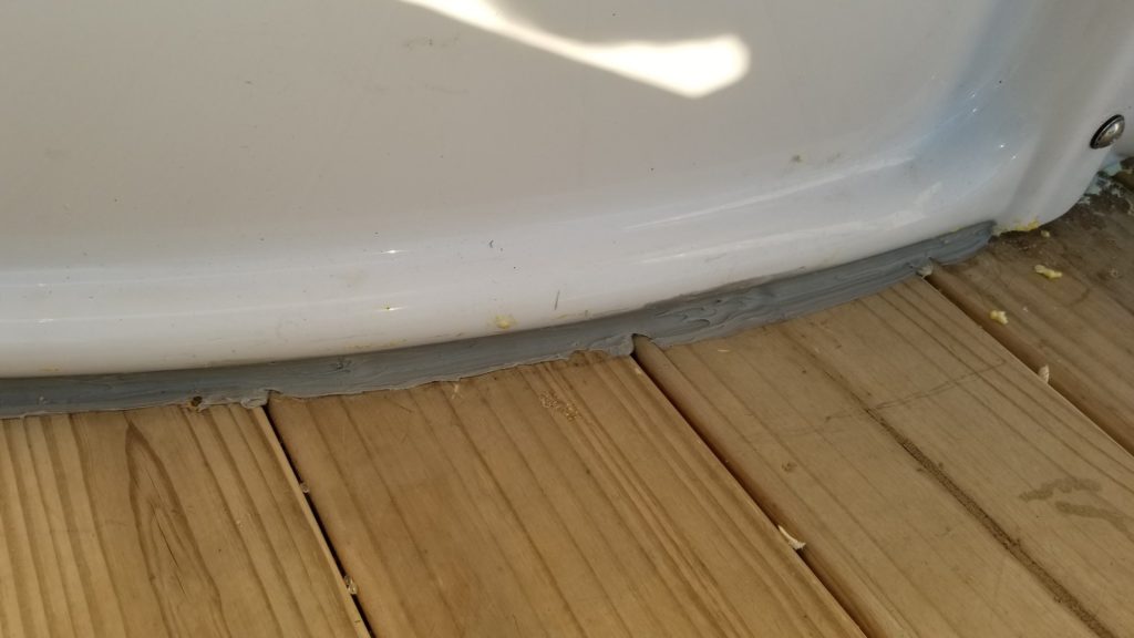
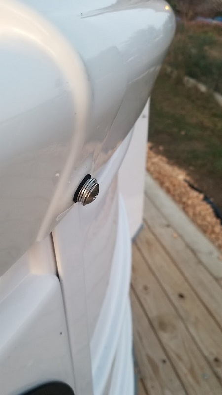
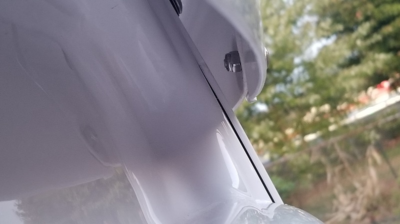
I had an issue with a bolt getting stuck as the dome rotated in one particular direction (always check both directions as i found out). I decided to remove the pl max premium and pl max premium 3x caulking (i used on inside) near this post that had the issue, as well as the one left of the door. It was very hard to chisel out the caulking, it really does stick and stick well to the deck! Quite happy about that. At any rate, i nudged them forward/inward about 1/2″ each, it gave more adequate clearance. Then i decided to go further, so instead of cutting bolts and risking threading issues, i added 4 washers to each to make less bolt on the other side, this was the result which worked out fine ever since then:
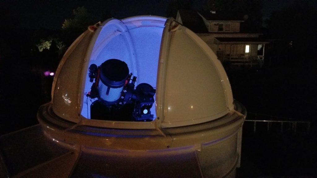
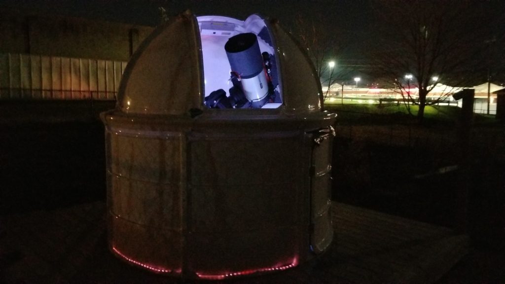
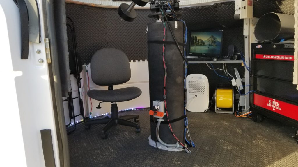
Also, you cant see, because blocked by the pier, but there is a small heater under the first bay. It comes in handy when you have to change optics beforehand, on a cold night (most of the time I am remote in my house in my office via RDP).
Shutter / Motor woes
Here is a clip showing the issue of the sticking with the motor (towards the end of the video). I’ve also since moved my magnet back another 1″ or so to get it closer on max zenith.
One other issue I ran into was the cog piece/pin falling out. This just needed the screw tightened and also the cog shifted to the right more to prevent the track from creating shavings.
On the shutter getting stuck, if i took the retention brackets off both sides there was no issue. I did really loosen the wheels to the point they wobble to help with avoiding the panels getting sandwiched and added extra washers there too. Ultimately it was the retention brackets for the most part, shortening the stubs on it helped, however there is still an issue today, where by midwinter the shutter would get stuck/jam mid way on closing in the park position. However in warmer temps no issue. I found that in the home position there was no issue closing so i’ve set my script that closes it, to make sure its home before closing.
Its worth mentioning that I also added a Foscam 1080 camera to the dome. It was placed on the post to the left of the left most bay looking in through the door. It comes in handy to make sure things are closed up at the end of the night and monitor things as the night goes on.
AAG CloudWatcher Setup and Software
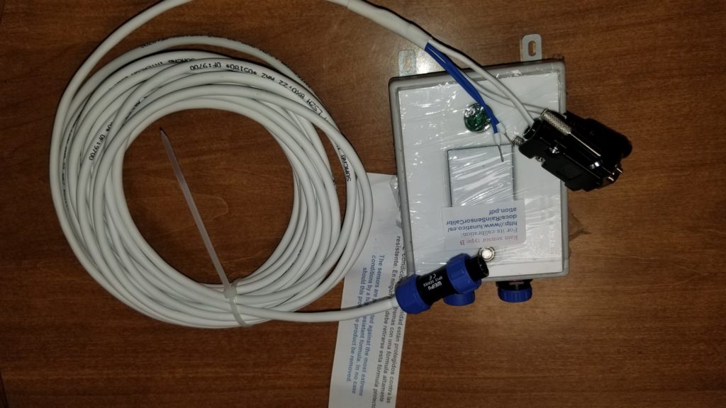
I purchased the AAG CloudWatcher unit, for detecting clouds and precipitation. The model I got requires a pc. It came with a very long serial connector. So in addition you need to pick up a usb to serial adapter from amazon, generally cheap around $10.
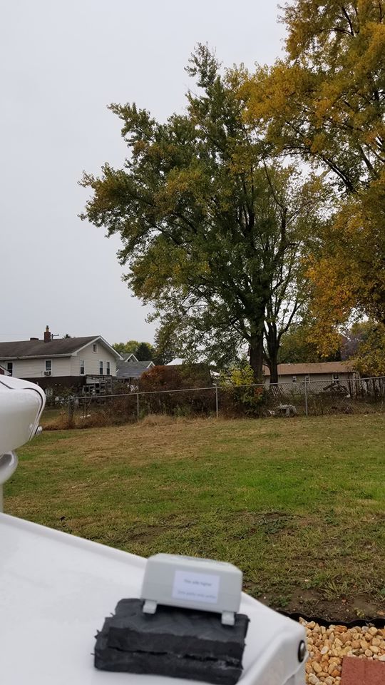
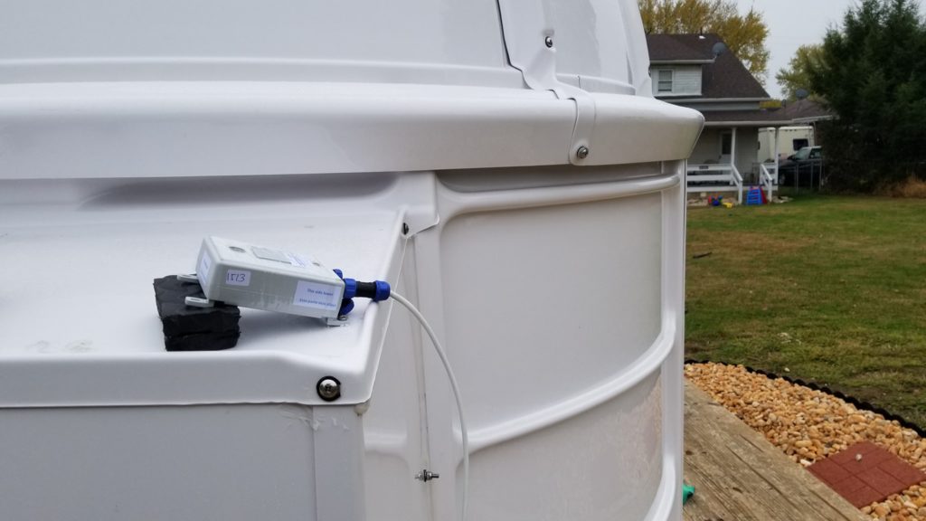
I ultimately went with the view to SW, since my direct west is blocked by tall trees. I could have also aimed it towards the NW (direction precip comes from for me). I drilled a hole in the back of the “Tool chest” bay and sent the wire outside to the left bay. On the left bay i used one screw into the material of the bay to secure it and used some leftover floor foam pieces to raise it up at the angle its to be installed at. The angle might still be too low and may need more propping, but so far its been ok.
The software can be found here. In the end all i needed was the software only 8.1.x installer installed for the main interface (master install). I did also install the AAGCWSafetyDriverSetup and the Boltwood.SafetyMonitorSetup.exe, those allow you to select boltwood in Nina and see the current weather conditions (i think both had to be installed and not just the AAGCWSafety one).
Some of the values in the software might need tweaked, especially depending on time of year like ones such as sky temperature limits (which can cause incorrect values being reported on sky conditions).
Note that the leads it comes with doesnt apply to the nexdome configuration. There isnt a spot in the motor unit to connect to. Everything is controlled via software, so those can be ignored.
In addition to the drivers, i also installed the Savant web portion, so i could connect remotely via a web page and see the stats.
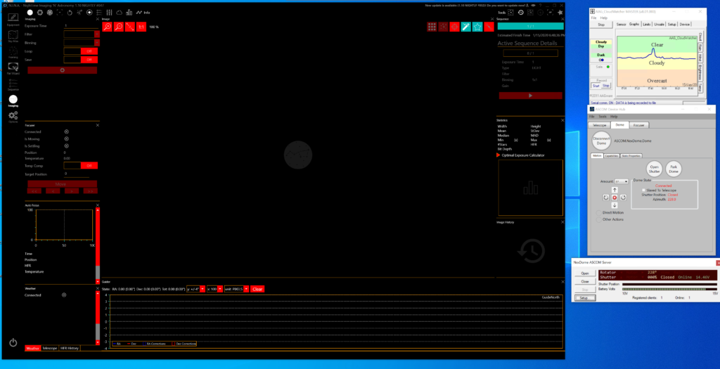
Here is the interface of the cloud watcher and the current settings i’m using:


Note that you must run the calibration steps for rain to get the correct dry/wet/rain values. Following the steps on the online guide. It basically involved a small drop of water, getting that value, then doing a much larger drop and getting that value.


In order to make the web page work, using Savant, some configuring is needed. The full document on how to do that is here. (The path below is actually a symbolic link to the cloudwatcher installed on D, more on this momentarily)

In the main root area there is an index.html which i modified to look like this:
<!DOCTYPE html PUBLIC "-//w3c//dtd html 4.0 transitional//en">

<HTML>

<HEAD>

<META HTTP-EQUIV="Content-Type" CONTENT="text/html; charset=iso-8859-1">

<TITLE>

The Orion Observatory AAG CloudWatcher Server

</TITLE>

</HEAD>

<BODY>

<CENTER>

<B><FONT FACE="Verdana"><FONT SIZE="-1">

Current conditions at - The Orion Observatory - as measured by the AAG CloudWatcher.</B><BR><BR>

Cloud cover <BR><IMG ALT="Cloud cover" SRC="../../../cloudwatcher/AAG_ImageCloudCondition.png"><BR><BR>

Brightness<BR><IMG ALT="Brightness" SRC="../cloudwatcher//AAG_ImageDayCondition.png"><BR><BR>

Rain<BR><IMG ALT="Rain" SRC="../cloudwatcher/AAG_ImageRainCondition.png"><BR><BR>

Temperature<BR><IMG ALT="Temperature" SRC="../cloudwatcher/AAG_ImageTemperature.png">


<BR><BR>

</CENTER>

</BODY>

</HTML>
To get the graphs to show on the web page, you have to either specify a subfolder under the savant install area or use a symbolic link to point to the actual cloudwatcher subfolder which has the pngs. In my case i left cloudwatcher set to its normal path as below:

So in the savant C drive folder i linked a subfolder using a symbolic link to the cloudwatcher on D and now those pngs are constantly updated and remain on my bigger/better D drive. Here is a shot of the actual folder structure, highlighted in yellow this is actually a symbolically linked folder to D as mentioned:

One of the best features of the software is being able to have a script run when it gets triggered to “Unsafe”. This has taken a lot of trial and error to get right with the dome and everything else, but i finally have a vbs script which i reference in the software. Ill put the script below for reference. Note i have a few parameters set to decide whether it even gets run. One is if Phd2 is running, if its not it skips it. Of course if the dome is open it should be run. But I would never be running the dome without phd2 running, unless of course phd2 decides to crash, then i’m screwed i guess. For now as below (and this same script i can manually run in a windows task scheduler task by picking a time after the last sequence is ran in Nina, or i can let the dome close it automatically via CloudWatcher when light is bright enough):
On Error Resume Next

Set objShell = WScript.CreateObject("WScript.Shell")
Const Timeout = 3


Function IsProcessRunning( strComputer, strProcess )
    Dim Process, strObject
    IsProcessRunning = False
    strObject   = "winmgmts://" & strComputer
    For Each Process in GetObject( strObject ).InstancesOf( "win32_process" )
    If UCase( Process.name ) = UCase( strProcess ) Then
        IsProcessRunning = True
        Exit Function
    End If
    Next
End Function


''wscript.sleep(3)
'objShell.Popup dome.ShutterStatus
'objShell.Popup dome.Connected
'objShell.Popup scope.Connected
'objShell.Popup dome.ShutterStatus


'If Err.Number <> 0 Then
'we have error
  ' Err.Clear
'End If
 'objShell.Popup scope.Connected

'if (dome.Connected = "True") and (scope.Tracking = "True") and (hub.Slaved = "True") Then
   'ElseIf (hub.Connnected = "True") Then

   'objShell.Popup "NOTGO"

'main if then check
if (IsProcessRunning("markm75o", "phd2.exe") = true) then
  ' objShell.Popup "GO"
    Set dome=CreateObject("ASCOM.NexDome.Dome")
     Set hub=CreateObject("ASCOM.DeviceHub.Dome")
     Set scope=CreateObject("ASCOM.iOptron2017.Telescope")
      dome.connected = true
       hub.Connected = true
       scope.Connected = true

while (dome.ShutterStatus = 4)   'Error - wait for shutter to go online
wend

if (dome.ShutterStatus = 0) AND ((IsProcessRunning("markm75o", "phd2.exe") = true) AND (hub.Slaved = True)) then
        'objShell.Popup "in the main DO IT HERE"
        'while dome.shutterstatus <> 0  '0 is open 1 is closed 4 is error 2 is opening  'in case of nexdome its 0 for BOTH open and closed
      hub.Slaved = False
      scope.Tracking = False
     dome.FindHome()
     wscript.sleep(135000)
   dome.CloseShutter()
      wscript.sleep(82000)
      dome.Park()
     wscript.sleep(42000)
   scope.Tracking = False

        dome.connected = false

       hub.Connected = false
      scope.Connected = false
        Set dome=Nothing
      Set hub=Nothing
        Set scope=Nothing

'kill the phd2 task
objShell.Run "taskkill /im phd2.exe /f", ,True
'objShell.Popup "after kill task"
   else

        'objShell.Popup "in false loop"


        'objShell.Popup "after scope tracking"
           dome.connected = false
        hub.Connected = false
       scope.Connected = false
       Set dome=Nothing
      Set hub=Nothing
      Set scope=Nothing
end if


else
'dont do anything dont connect to shutter etc


end if
Also, to get cloudwatcher to start when windows starts, i created a vbs file and i launch that at startup:
Dim oCW

set oCW = CreateObject("AAG_CloudWatcher.CloudWatcher")

oCW.Device_Start()

oCW.RecordStart True

Set oCW=nothing
Software Dome Configuration, Control, Scripts, Nina and Other Issues
Getting the slot to align with the scope at the right position was initially very challenging. I went so far as to use a laser measurement device to figure out where the exact center of the dome was and how much N/S and E/W drift from that point, the mount was. In the end these measurements didn’t matter much. It was trial and error getting things to align properly, adjust a value here and retest etc. The one that might have held more value was getting the center of the optical axis to the center of the RA/Dec cross point. Once I had that figured out I was able to tweak this setting (Gem Axis offset).
Initially I was using Ascom Control Panel to configure everything. Ive moved on to the Ascom Device Hub. One drawback, it doesnt seem to have a park option. But my park value (which currently is at 228) I can enter manually if i need to. Usually its a script firing at the end of the night that does it for me.

Here are the settings I ultimately went with in Ascom Device Hub. Yours will differ most likely, but the value that could be relevant is the Gem Axis Offset value for the cem120 (mine took into consideration the finder scope which is a 60mm Svbony).

The NexDome software / driver is found here NexDome Control System 3.0.1 and of course you should have the main ASCOM driver set installed as well.
This software is what gives you the interface to see the voltage and other values as here:

These are the setup values I’m using. I lowered the speed and ramp time a bit to help reduce the chance of binding. Not sure that the values have helped or not:

The latest firmware are found here on GitHub, also a good area to report issues, beyond just the FaceBook NexDome Group. You can update the firmware via the Update Firmware button (when not connected to Ascom). If things are working, however, its probably best to avoid updating it to cause new issues.
One of the biggest issues, especially when doing alot of work remotely using RDP is windows disappearing and not reappearing. Ascom Device hub recently started vanishing on starting. The only way i could get it to reappear was by going into Windows 10 Task Manager and right clicking the icon as seen below and selecting “maximize”

The usual trick of hovering over the item in the taskbar and selecting maximize didn’t work (does not exist for Ascom Device Hub, but does for the NexDome Control Panel).
In the event you cant get NexDome Control Panel to appear, even by the taskbar, you can use the Ascom Profile Explorer Tool and drill into the NexDome area and change the MainFormLocation to 0,0 as below:

The script that I mentioned in the CloudWatcher section, above, as I briefly mentioned, is referenced in a Task Scheduler Task. Ill load up Nina, determine when the last sequence will end, add some more time to that (say 20-30min extra to be safe) and do the scheduled task to have it close the dome, rather than waiting till sunlight hits the cloudwatcher to close. Here is the example Task Scheduler settings:


I now use Nina as my primary DSO imaging platform. I havent ever used SGP and I don’t believe I will need to. So far it has all the features I need. For planetary I still use SharpCap Pro.
The Digital Loggers Web Power control unit has a way to control it via scripting as well. This way outlets can be controlled from script to turn on or off:
https://www.digital-loggers.com/lpc7faqs.html
VBS Code example:
Imports System.Net
  Imports System.IO
  Imports System.Text

  Module Module1

    Sub Main()
        Dim webResponse = ""
        Dim req As HttpWebRequest
        Dim res As HttpWebResponse
        Console.ReadKey() ' hit a key to turn the switch on
        req = WebRequest.Create("http://192.168.0.100/outlet?1=ON")
        Dim Encoded As String = System.Convert.ToBase64String(System.Text.Encoding.UTF8.GetBytes("admin:1234"))
        req.Headers.Add("Authorization", "Basic " + Encoded)
        res = req.GetResponse() ' Send Request
        Console.ReadKey() ' hit a key to turn the switch off
        req = WebRequest.Create("http://192.168.0.100/outlet?1=OFF")
        req.Headers.Add("Authorization", "Basic " + Encoded)
        res = req.GetResponse() ' Send Request
        Console.ReadKey() ' hit a key to exit program
    End Sub

  End Module
This script can then be ran at the end of the batch file that I use in this case, to close the dome, shutting off the power to the DC and turning on the power to the Dehumidifier.
Remaining NexDome Issues
UPDATE: see the last section, these whip antennas were NOT the answer, the xbee 3 pro’s were.
To date I’m still battling various issues. More recently I had a ton of communication timeouts and errors with the NexDome Control Panel. Basically the shutter and rotator will not communicate at times.
To combat this I ordered a replacement Xbee unit for both in the Rotator box and in the Shutter Motor box. So far this has been significantly better as a result. There are still disconnect issues but those seem to be driver related.
The part I used to replace the xbee’s is part number XB24-AWI-001
The key to this one being better is the hard wire antenna that is attached. If you are lucky and have an Xbee unit that has the antenna jack, you can just attach an external one and not change it out.

Despite much better connect success, randomly the Control Panel reports “Offline Configuring”, which according to some support folks, this means there is a glitch in the driver (possibly) causing this to occur.
Often times though, even power cycling the Rotator box alone is not enough. You either have to go out and power cycle the Shutter motor, or if both fail I’ve found the only solution is to use Putty and connect via the terminal (only works a small percentage of the time) and then reconnect. Other times I find that I have to issue the Rotator firmware update hex file via the Update Firmware button and then after power cycling things it suddenly connects again. This is very frustrating.
The other shutter disconnect issue is that when you hit the stop button on the Ascom Device Hub or even the older Ascom Control Panel, whether its the rotator or the shutter stopping, it will cause instant communication failure and then the whole thing needs power cycled or doing the firmware update trick to restore communication.
I still have the lingering issue of the one “bump” between panels causing the motor to stall as mentioned before (only in the one spot where the wheel suddenly rides up on the edge more than any other wheel). Again, I’m hoping just some filler in that gap will help and i dont have to tear everything apart so i can pound that post outward 1/2″ (power panel bay/post area).
The other issue was the shutter getting stuck, which i reported as fixed previously but have mentioned that after cold weather hit, its still an issue but only in the “park” position at 228 degrees. However, when it warmed up, I retested the shutter in that position and it closed without issue. It may have been related to lowering the shutter speed in the software, unsure. Someone in the group has mentioned that you can change the dip switch positions to force a slower shutter speed than even the software will allow, but if you do this you have to change it in the software. The shutter will take 2 minutes to close instead of 1.
Here are more details on the dip switch settings:
The default for v3.x firmware is 8micro steps w/ 1600 pulse/rev (S1-OFF; S2-ON; S3-OFF) or about 46000 steps.
The slower setting is as follows: 4 micro steps / 800 pulse/rev (S1-ON; S2-OFF; S3-OFF) ( This doubles the rotation speed and halves the total number of steps from fully closed to fully open to something ). In the software you then use a setting of 470 and acceleration of 900 (the same settings on default dip switch might take 2 minutes to open).
One other possible fix for the shutter sticking is Meguiar’s Ultimate Quick Wax off amazon for $9.99, this is a less permanent solution. I also had used the slick tape (TapeCase 423-5) on all sides of the shutter when I first encountered this issue, it only marginally helped. I tried added more recently with the newer issue, it didnt help at all.
One note, if the shutter sticks and doesnt fully close, it throws the software panel off. You have to manually go out and close the shutter (though Tim in support of the software has said there may be a way to force it via script). Even if you do get it to close by software or manually, the closed state “altitude” reading will be off. I’ve found the quickest way to “reset” it was via the update firmware button and updating the rotator with its firmware .hex file.
Also, in my case, I have to send the dome to home then to park to get the contacts to line up each time for the charger. The contacts get pushed left or right depending on which way the dome is rotating and as a result dont hit the contacts for charging, unless you do the home/park trick, which my script above references. And the contacts that extend down from the motor have had the screw/nut come loose and fall off at one point. I added some moldable glue to each of them, now they wont fall off (regular glue would work too, or locktite).
Conclusion
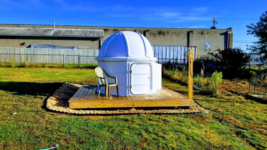
Despite the issues listed above, I’m happy overall with the dome. Yes there were many issues during construction, some not helped by poor instruction manual diagrams (very limited instruction provided). I found myself asking alot of questions on the group on facebook to figure things out.
Yes there are some possible firmware issues causing the shutter to hang, but I would hope over time those will get worked out and for now I now have a few workarounds to get it closed remotely in the worst case.
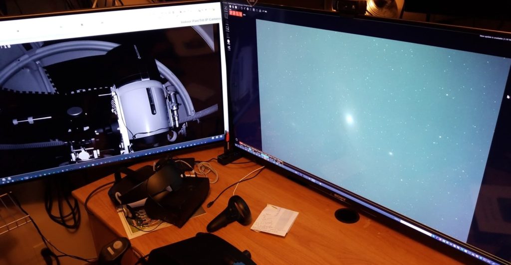
I wouldn’t want to go with a dome design that wasn’t one like the NexDome. The light/wind shielding is invaluable to me in the city and is slightly more secure, especially with the automation of the shutter closing. I have the option too of going out to the dome or doing everything from my office in my house. On one screen I can place the remote foscam view and on the other the RDP session to the i7 machine in the dome.
This wasn’t meant to be a review, but if i had to rank various features 1-10, i’d say the following to be my opinion (probably a category or two missing here):
Value: 10.0
Features: 8.0
Reliability: 6.0
Overall: 7.0
(lots of tweaking and hair pulling at times, but most of the time things are fine)
NexDome Construction and Wrap Up YouTube Videos
Full List of Equipment and Accessories
NexDome with 2 Bays
NexDome Rotation Kit
NexDome Shutter Kit
AAG CloudWatcher
Xbee XB24-AWI-001 x 2
LifeP04 Charger (for times the shutter battery fails to connect and recharge properly)
Adhesive Clips for random wires on dome
i7 6770hq Intel Skull Canyon NUC NUC6i7KYK
2TB Rocket Nvme SSD Secondary Drive for HighSpeed Planetary Capture
8TB Raid5 array(2tbx5) in Oyen Mobius 5 Bay across gigabit for DSO
22″ Viewsonic 1080P LCD
CyberPower APC UPS
Web Remote Control Digital Loggers (ethernet)
Smart Plug Wifi Outlet for Heater (overloads the ups if not isolated)
Foscam R2C 1080 Camera
Lowes Tool Chest
PL Max Premium (outside base of walls)
Standard 10 year caulking for any other cracks
PL Max 3X (inside base of walls)
3/4″ Foam Mats for the floor
1/2″ Foam Mats for the walls/dome x 3
Bug Netting
TapeCase 423-5
Heater 1500w/750w adjustable with thermostat
Rinkmo 30 pint Dehumidifier with drain hose
Gunsafe Dehumidifier Rod for in drawer
Stanley Fan (summer time use, pre-sessions)
TPLink AC2600 Wifi Extender (Unify networks dual ac pro’s more ideal for roaming)
DC Power Supply PowerWerx 30amp SPS-30DM 5-16 Volts
RIGrunner 4008
DX Engineering Zip Cord Power Wire DXE-PW-12 19 feet
DX Engineering Zip Cord Power Wire DXE-PW-18 14 feet
Ecowit Weather Monitor
Krylon Fusion Matte Black spray paint
32 feet LED lights with remote control
4 foot 10″ PVC Pipe (local vendor)
iOptron Cem120 Mount
iOptron Cem120 Mount plate
Custom secondary plate for cem120 (local fabricator)
Celestron 11″ EdgeHD
Anker 10 Port USB Hub for on CEM120
Svbony 60mm Guidescope
Asi290mm Mini for Guidescope / OAG
Celestron OAG
Asi294mc Pro
Celestron F7 Reducer
Dew Heater
Hyperstar V3
Hyperstar 3D Printed wire holder
Celestron Dew Shield
Spike-A-Flat Flat LED Panel with USB controller
Enhancements and Updates
Shutter Disconnect Fixes (March 2021)
For quite some time now I’ve had issues with the shutter disconnecting and getting stuck (to the point the power button has to be toggled in order to even physically get it to move via its button). I first tried replacement Xbee Units with attached whip antennas, but they only helped marginally. These new Xbee Pro v3s + 2.4ghz stick on antenna’s turned out to be the key. You will need the USB module to update the Xbee units to 802.15.4 firmware (they come with the Zigbee firmware, so that wont work).
To install the firmware, which i believe is part of the software. You need the XCTU download located here (I used the windows version). Place the xbee unit in the reader and connect the usb, then the XCTU software finds the radio, you can then select the 802.15.4 firmware and flash (do this for each module)

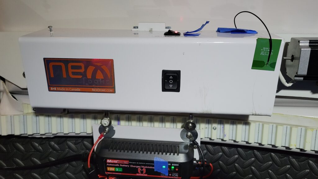
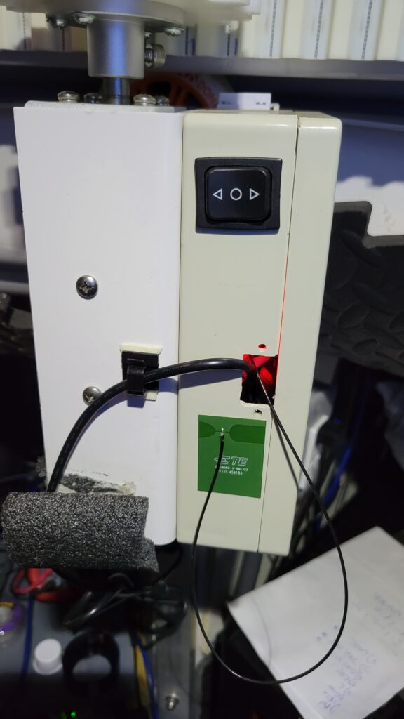
Then you turn off the rotator and shutter and swap out the modules, attaching the stick on antenna to each (I sent the wire through the hole on the right side of the shutter box and stuck the antenna on the right side/front of the shutter box and front of the Rotator). Will try to add a photo here later.
***NOTE*** Dont be alarmed if at first the shutter doesnt want to connect, i cant recall the specifics, but some order of powering off the rotator and or shutter and suddenly it connected up just fine and has been connecting up instantly and consistently ever since
Here are the parts needed (replacing both xbees in both the rotator and shutter motor area):
Xbee V3 x 2 $29 each WRL-15129
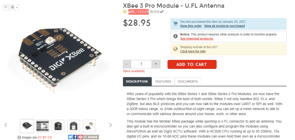
2.4ghz UFL Connector stick on antenna WRL-11320

Xbee USB Adapter for firmware flashing $13 via amazon
Xbee USB Adapter for firmware flashing $13 via amazon

Some shots of the antennas attached


im watching you neighbor
Great information Mark. I am in the process of setting up my NexDome…platform has been finished, now on to the Dome install. I don’t expect my install to be as elaborate as yours…yet, Lol. Thanks, Jim G.
Hi Mark, Thank you for the detailed documentary of your observatory build. I referenced this article and your youtube videos many times while making my observatory. For someone who is willing to go all in with an observatory, but is new to assembling the whole package, your information has been vital. Many of the components of my observatory are the same as yours, though there are some major differences too. I went with a concrete pad separated pier. This required a rethink on the insulating floor. The rotator – shutter communication initially never worked and I needed to get XBee… Read more »
Hi there. I’m glad my info was of use. The concrete pad sounds nice. How does that cool down thermally for you where you are though? Have you compared outside vs inside temps after a cooldown period? For my deck even being 12 inches off the ground or so, i’m finding the inside temp of the dome is often 4F warmer than outside. I thought at first it was the foam padding i added to reduce reflection inside the dome, but i tore those off temporarily and retested, same difference. It doesnt seem to hurt the images too much though.… Read more »
Last night there was a difference of 2.5 – 4 degrees F (avg. 3F), but it was also in the 40s last night. Colder or hotter outside temperatures as compared to ground temperature could results in a bigger delta. Have to check on that. For the concrete pad inside the obs, I put DMX 1-step on first, then the same black foam pad you used on top of the DMX. The DMX 1-step allows the concrete to breath in case there is some rain or melting snow, but it also insulates. I left about 1/2″ of concrete pad exposed around… Read more »
Thank you for this detailed description. I’ve just purchased a Nexdome and finding information is almost impossible. I’ve had an application in to the Nexdome Forum and Facebook Forum for two weeks had haven’t heard a peep about being accepted. The only other source is Babek and web pages like yours. Thanks again. I’m sure I’ll be revisiting your site a number of times.
Hi there, thanks for visiting. You requested the FB group, we love our nexdomes right? The old group is offline/not active anymore. Good luck on the build, Mark
Thank you providing all this fabulous information. Thank you
amazing article
Just a question on xbee upgrade, did you only update the firmware or had to change other fields in the xbee?
My rotator was missing the xbee and bought one locally and trying to understand how to make it talk to the shutter
Hey there, Thanks for stoppin by.
I believe i just used the updater usb device, put the xbee in, used their firmware update interface (picked the matching firmware) and hit update. I dont think any other fields were changed. It took a couple of power cycles to fully work after it was back in the shutter/rotator.
Hi Mark. I bought these parts right after you posted this. But I never installed them. So I was wondering how its worked out for you. Are you still using it with no issues?
Hi there,
Which parts specifically, or all of the dome you mean? Everything is still going strong for me, well except for the clouds around here last few months 🙂
Mark